
Overview
Allen-Bradley 1791-32A0 Retrofit-Ready Block I/O for Legacy 1791 Series Control Systems
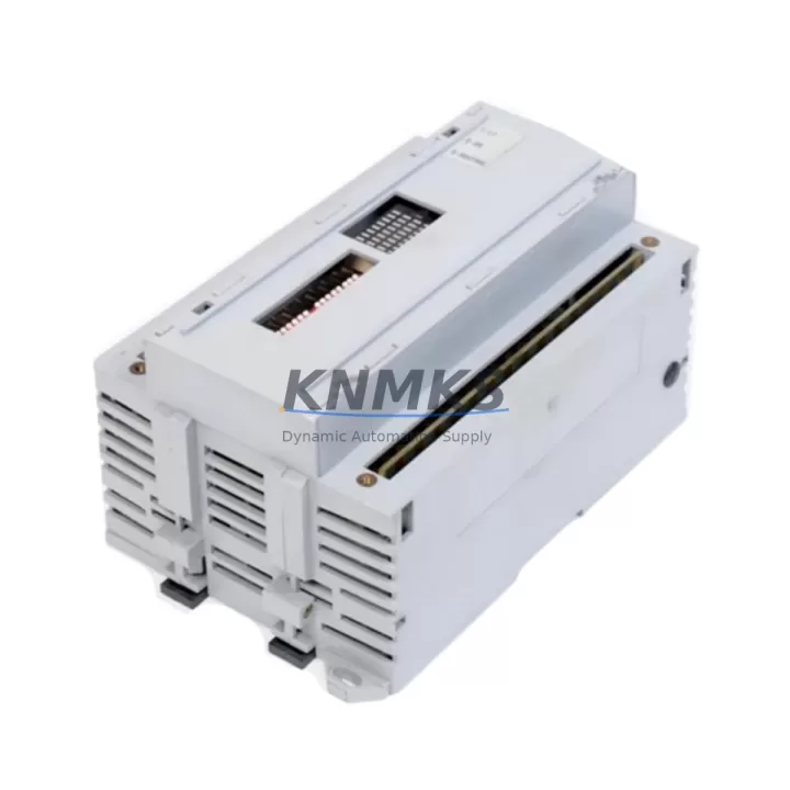
The Allen-Bradley 1791-32A0 is a 32-point AC Block I/O module designed for distributed I/O architectures built on the 1791 Series platform. As legacy control systems face end-of-life pressures and original spare parts become increasingly scarce, the 1791-32A0 remains a critical component for engineers managing retrofit projects, panel upgrades, and production line modernization. Whether you are replacing a failed unit in an aging control cabinet or executing a planned migration from an obsolete automation platform, this module provides a verified, drop-in compatible solution that minimizes engineering rework and reduces unplanned downtime.
The 1791-32A0 accepts 120V AC discrete inputs and outputs across 32 points, making it well-suited for machine-level control tasks where AC field devices — including solenoid valves, motor starters, and pilot lights — are wired directly to the block. Its compact footprint and DIN-rail or panel-mount installation options allow it to fit within existing control cabinet layouts without requiring structural modifications, a key advantage when downtime budgets are tight and physical space is constrained.
Migration Compatibility Table
| Parameter | 1791-32A0 Specification | Retrofit / Migration Notes |
|---|---|---|
| I/O Points | 32-point (16 IN / 16 OUT) | Verify field device count before replacement; re-use existing terminal wiring where possible |
| Input Voltage | 120V AC | Confirm panel supply voltage matches; incompatible with 24V DC variants (e.g., 1791-32B0) |
| Communication Interface | 1791 Series Block I/O bus | Requires compatible 1791 adapter module on the same network segment |
| Installation | Panel mount / DIN rail | Check cabinet depth and mounting hole pattern against original unit |
| Address Configuration | Rotary switch (node address) | Record original address setting before removal; re-apply on replacement unit |
| Firmware | Hardware-based (no firmware update required) | No firmware compatibility risk; verify adapter module firmware if upgrading scanner |
| Replacement Path | Direct 1791-32A0 replacement | For platform migration to ControlLogix, consider 1734 POINT I/O with 1734-AENT adapter |
| Support terms | support terms confirmed by quotation | Covered from date of shipment; includes functional verification and burn-in test |
Retrofit Planning for Existing Automation Systems
Successful integration of the 1791-32A0 into an existing control system requires careful pre-installation planning. Before removing the failed or obsolete module, engineers should document the current node address set on the rotary switch, photograph or record all terminal wiring connections, and confirm that the replacement unit’s I/O point configuration matches the original. In systems where the 1791 Series adapter — such as the 1791-A2B or a compatible remote I/O scanner — is still in service, no changes to the communication link are required. However, if the retrofit is part of a broader platform upgrade, the adapter module itself may need to be replaced or reconfigured.
In control cabinets where the 1791-32A0 operates alongside a 1747 SLC 500 processor or a 1785 PLC-5 controller, the I/O map and rack/slot addressing in the ladder logic program must be verified before the replacement module is brought online. If the slot address or rack number has shifted due to hardware changes elsewhere in the system, the program will require corresponding edits before the machine can resume normal operation. This is a common source of extended downtime during unplanned replacements and should be addressed during the pre-outage planning phase.
For systems that include a 1771 I/O chassis or a 1746 SLC I/O rack in the same control cabinet, the 1791-32A0 operates independently on the Block I/O network and does not share backplane resources with chassis-based modules. This architectural separation simplifies the replacement process but also means that any communication issues between the block and the scanner must be diagnosed at the network level rather than through the backplane. Checking the 1791 adapter’s status indicators and verifying the remote I/O cable termination resistors are correctly installed are standard first steps in troubleshooting communication faults after module replacement.
Where the retrofit scope extends to upgrading the HMI, engineers should verify that any tag references or data file addresses mapped to the 1791-32A0’s I/O points in the HMI project — whether running on a PanelView 550 or a more recent PanelView Plus terminal — remain consistent with the updated PLC program. Mismatched addresses between the controller program and the HMI configuration are a frequent cause of post-retrofit alarm and display errors that extend commissioning time. Completing a full I/O forcing test on the replacement module before closing the cabinet and resuming production is strongly recommended.
Downtime Control During System Migration
Minimizing production downtime during a 1791-32A0 replacement begins with preparation completed before the maintenance window opens. A pre-staged replacement unit that has been visually inspected, address-configured, and functionally tested off-line can reduce the physical swap time to under 30 minutes in most installations. The original PLC program should be backed up to an offline copy before any hardware changes are made, ensuring that the control logic can be restored quickly if unexpected issues arise during commissioning.
Where the control system supports partial I/O scanning or fault-tolerant operation, it may be possible to isolate the failed 1791-32A0 node and continue operating the remainder of the machine on reduced I/O while the replacement is prepared. This approach is particularly valuable in multi-zone production lines where shutting down the entire line to replace a single block I/O module would result in disproportionate output losses. Coordinating with the production team to schedule the swap during a planned break or shift change further reduces the operational impact.
After the replacement module is installed and the system is powered on, a structured commissioning sequence — verifying communication status on the adapter, forcing each I/O point individually, and confirming correct response at the field device — provides confidence that the replacement is functioning correctly before the machine is returned to automatic mode. Retaining the original failed module for post-mortem analysis can also help identify root causes such as voltage transients, moisture ingress, or mechanical damage that may affect other modules in the same installation.
Retrofit Support FAQ
Q: Is the 1791-32A0 a direct replacement for other 1791 Series Block I/O modules?
A: The 1791-32A0 is a direct replacement for other 1791-32A0 units. It is not directly interchangeable with 24V DC variants such as the 1791-32B0 or with modules that have a different point count or terminal configuration. Always verify the exact catalog number before ordering a replacement.
Q: Does the replacement module require any firmware update or configuration download?
A: No. The 1791-32A0 is a hardware-configured module with no firmware to update. Node address is set via rotary switch. No software download is required to the module itself, though the PLC program should be verified for correct I/O addressing after installation.
Q: What wiring checks should be completed before powering on the replacement module?
A: Confirm that all field device wiring is reconnected to the correct terminals using the original wiring diagram or photographs taken before removal. Verify that the AC supply voltage to the module matches the 120V AC rating. Check that the communication cable to the 1791 adapter is securely connected and that termination resistors are in place at the ends of the remote I/O network segment.
Q: What does the support terms confirmed by quotation cover, and how is stock availability managed?
A: Each 1791-32A0 unit ships with a support terms confirmed by quotation covering functional defects from the date of shipment. Prior to dispatch, units undergo functional verification and burn-in testing. Stock is maintained to support urgent replacement requirements. Contact our sales team for current availability and lead time confirmation before placing a critical-path order.
© 2026 KNMKS. All rights reserved.
Original Source: https://knmks.com
Contact: admin@knmks.com | +86 18359268345
Product Identification
- Brand / Ecosystem
-
Allen-Bradley
Allen-Bradley - Model / Series
-
1791-32A0
Assorted Series - Product Family
- PLCs & Controllers
- Availability Status
- Available on request after model and quantity confirmation
- Inquiry Type
- B2B RFQ, replacement inquiry and project spare-part request
- Pre-Quote Check
- Exact SKU, brand, series, quantity, nameplate photos and destination country are checked before quotation
System Path
Where this product fits in the KNMKS automation structure.
Specification & Inquiry Focus
- Control platform
- PLC, PAC and modular controllers
- Common needs
- CPU, rack, power and I/O expansion
- Project support
- Replacement, cabinet build and maintenance
Buyer Confirmation
Information KNMKS checks before replying.
- Exact model
- 1791-32A0
- Brand / ecosystem
- Allen-Bradley
- Product family
- PLCs & Controllers
- Application note
- Replacement, maintenance, project build or spare-part list
- Useful photos
- Nameplate, installed unit, cabinet layout or connector side
- Delivery details
- Quantity, destination country and target schedule
Document Support
Files and notes can be confirmed during quotation.
- Product photos or nameplate confirmation when available
- Packing and delivery notes before quotation confirmation
- Support scope and delivery terms confirmed per inquiry
- Export document coordination for qualified B2B requests
Inquiry Support
- Model cross-checking before quotation
- CPU, power, rack and expansion module matching
- Support for replacement and project inquiry
What to Send Us
- Brand and exact model number: Allen-Bradley 1791-32A0
- Quantity and required delivery time
- Application, replacement requirement or nameplate photo
- Destination country and shipping preference
RFQ Preparation
This is a product inquiry page built for RFQ communication.
Fast Model Check
Send this model to KNMKS for confirmation.
Include quantity, destination country and photos if this is a maintenance replacement. The inquiry will be saved with a reference number after submission.
Brand & Compatibility Note
KNMKS displays automation product information for well-known industrial brand ecosystems and compatible replacement references. Brand names are used for product identification and compatibility reference only; final availability and commercial terms are confirmed per quotation.
 Manufacturing
 Machine Tools
 Packaging
 Energy & Power
 HMI & Displays
 Servo Systems
 Variable Frequency Drives
 Sensors