
Overview
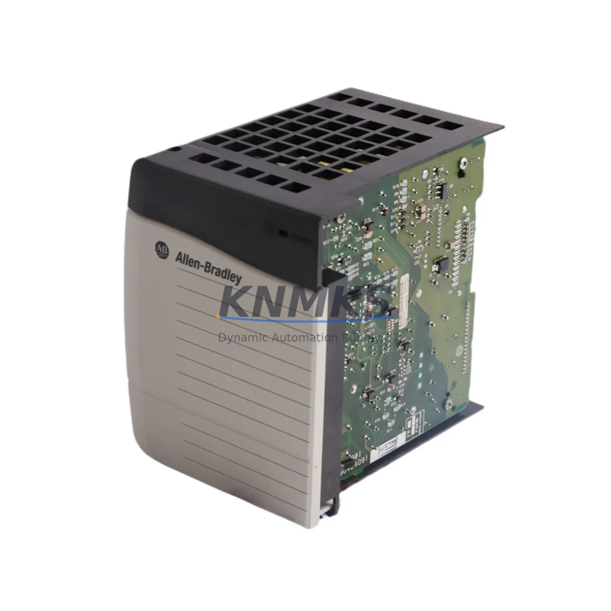
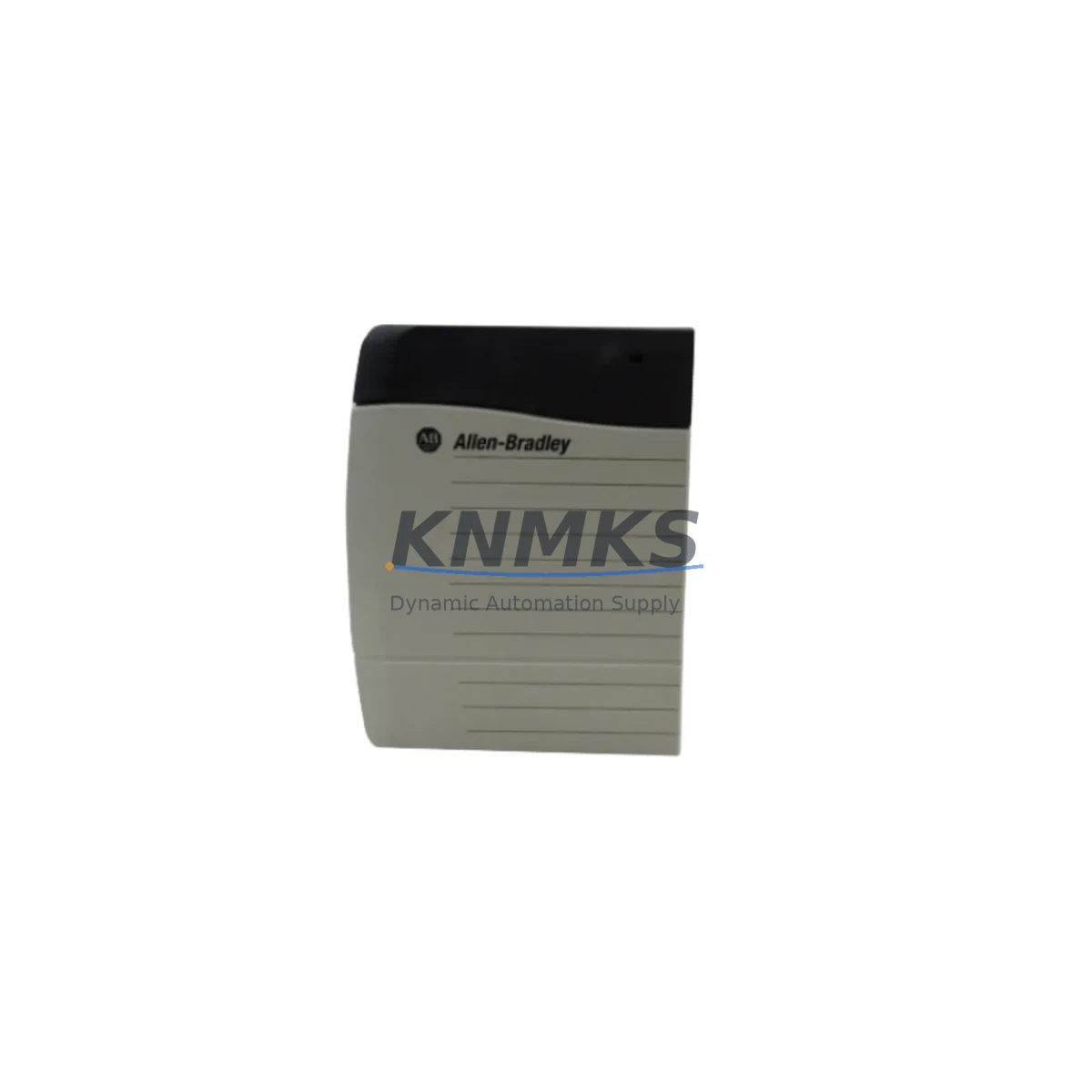
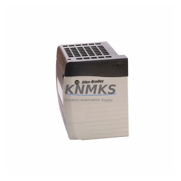
Allen-Bradley 1756-PB75 Migration-Ready DC Power Supply for Legacy Control Systems
The Allen-Bradley 1756-PB75 is a 75W DC input power supply module designed for the ControlLogix 1756 chassis platform. As legacy ControlLogix installations age and original power supply modules approach end-of-life, the 1756-PB75 serves as a verified drop-in replacement for facilities managing long-running production lines, process control cabinets, and distributed I/O architectures. Whether you are executing a planned retrofit, responding to an unplanned failure, or building a spare-parts inventory to extend system life, the 1756-PB75 delivers the electrical performance and mechanical compatibility required for seamless integration into existing 1756 chassis without reprogramming or hardware redesign.
This module accepts a 19.2–30VDC input range and delivers regulated power to the ControlLogix backplane, supporting mixed-module configurations that include analog I/O, digital I/O, communication bridges, and motion control cards. Its compact form factor occupies a single slot in any standard 1756 chassis — including the 1756-A4, 1756-A7, 1756-A10, 1756-A13, and 1756-A17 — making it directly interchangeable with earlier 1756-PA75 AC variants when the control cabinet has been converted to a DC power distribution architecture.
Migration Compatibility Table
| Parameter | 1756-PB75 Specification | Retrofit / Migration Notes |
|---|---|---|
| Input Voltage | 19.2 – 30VDC | Verify DC bus voltage at cabinet before installation; confirm UPS or rectifier output matches range |
| Output Power | 75W continuous | Audit total backplane load across all installed modules; replace with 1756-PB75/B revision if load exceeds 60W average |
| Chassis Compatibility | All 1756-Axxx chassis (4, 7, 10, 13, 17 slot) | No chassis modification required; module slides into slot 0 position per standard ControlLogix layout |
| Backplane Interface | ControlLogix standard backplane connector | Inspect backplane connector pins for corrosion or mechanical wear before seating replacement module |
| Terminal Wiring | Screw-terminal DC input block | Retain original wire labels; confirm polarity markings before reconnection; torque to 0.56 N·m |
| Communication Compatibility | Passive — no protocol dependency | No firmware update required on communication modules (e.g., 1756-EN2T, 1756-DHRIO) after power supply swap |
| Firmware / Software | No embedded firmware | Existing Logix Designer project files and controller firmware are unaffected by power supply replacement |
| Installation Space | Single-slot, standard 1756 form factor | Confirm slot 0 clearance in cabinet; check adjacent module spacing for airflow |
| Replacement Path | Direct replacement for 1756-PB75, 1756-PB75/A, 1756-PB75/B | Cross-reference catalog suffix with original module label before ordering |
| Support terms | support terms confirmed by quotation | Covers manufacturing defects; includes pre-shipment functional test report on request |
Retrofit Planning for Existing Automation Systems
Successful integration of the 1756-PB75 into a legacy ControlLogix system begins well before the module arrives on-site. A structured retrofit plan reduces risk, shortens commissioning time, and protects the integrity of the existing control program.
Power Budget Audit: Before ordering, document every module installed in the target chassis. Sum the backplane current draw for each card — including the 1756-L7x or 1756-L8x controller, any 1756-EN2T or 1756-EN3TR Ethernet communication modules, analog input/output cards such as the 1756-IF16 or 1756-OF8, and any installed 1756-DHRIO Data Highway Plus bridge modules. The 1756-PB75 provides 75W of backplane power; if the calculated load approaches this ceiling, consider redistributing modules across a second chassis or upgrading to a higher-capacity supply.
Terminal and Wiring Verification: The 1756-PB75 uses a removable screw-terminal input block. Before disconnecting the failed or aging supply, photograph the existing wiring, label each conductor, and record polarity. DC-powered cabinets often share a common negative bus with other field devices; confirm that the replacement module’s negative terminal is isolated or bonded per the original cabinet design. If the cabinet also houses a 1756-PA75 AC supply in a redundant configuration, verify that the DC and AC input circuits remain electrically separated.
Backplane and Chassis Inspection: Remove the old power supply and inspect the chassis backplane connector for bent pins, oxidation, or debris. In installations where the original module has been in service for more than five years, it is advisable to clean the backplane connector with an appropriate contact cleaner before seating the replacement. If the chassis itself shows signs of physical damage or connector wear, consider replacing the 1756-A7 or 1756-A10 chassis concurrently to avoid a repeat failure.
Controller and Program Integrity: The 1756-PB75 is a passive power component with no embedded firmware. Replacing it does not alter the controller’s memory, project file, or I/O configuration. However, if the controller is a 1756-L61 or 1756-L62 without a 1756-ESMNSE energy storage module, a power interruption during the swap will clear the controller’s RAM. Back up the Logix Designer project to a CompactFlash card or laptop before beginning work. For controllers equipped with a 1756-ESMNSE or the integrated energy storage on 1756-L8x series, the program is retained through brief power interruptions.
HMI and SCADA Continuity: If the ControlLogix chassis communicates with a PanelView Plus HMI or a SCADA system via EtherNet/IP through a 1756-EN2T module, the HMI will display a communication fault during the power cycle. Notify operators in advance, place the process in a safe hold state, and confirm that the HMI reconnects automatically after power is restored. No HMI screen reconfiguration is required.
Downtime Control During System Migration
Minimizing production downtime during a power supply replacement requires coordination between maintenance, operations, and engineering teams. The following approach is recommended for facilities where the ControlLogix system controls a continuous or semi-continuous process.
Pre-Shutdown Preparation: Schedule the replacement during a planned maintenance window or shift changeover. Prepare the 1756-PB75 replacement module, a calibrated DC power source for post-installation verification, a laptop with Logix Designer loaded and the current project file backed up, and a wiring diagram for the cabinet. If the system includes redundant power supplies, confirm that the standby supply is functional before taking the primary offline.
Controlled Power-Down Sequence: Place the controller in Program mode via Logix Designer before cutting power. This ensures that all output modules de-energize in a controlled state rather than dropping unpredictably. For systems with 1756-OB16 or 1756-OA16 digital output modules driving field actuators, confirm that the process is in a safe hold condition before proceeding.
Module Swap and Verification: Remove the old 1756-PB75, seat the replacement, reconnect the DC input terminals, and restore power. The module’s status LED should illuminate green within seconds. Use Logix Designer to confirm that the controller returns to Run mode, all I/O modules report healthy status, and communication modules re-establish their EtherNet/IP or ControlNet connections. A typical swap, including wiring verification and controller status confirmation, can be completed in under 30 minutes by a trained technician.
Post-Installation Documentation: Record the replacement date, module serial number, and any observations about the failed unit. Update the cabinet’s maintenance log and spare-parts inventory. If the removed module shows signs of capacitor bulging, burn marks, or terminal corrosion, retain it for root-cause analysis to determine whether the failure was caused by input voltage transients, overloading, or environmental factors.
Retrofit Support FAQ
Q: Is the 1756-PB75 a direct replacement for the 1756-PB75/A and 1756-PB75/B catalog numbers?
A: Yes. The 1756-PB75, 1756-PB75/A, and 1756-PB75/B are functionally and mechanically interchangeable within the ControlLogix 1756 chassis platform. The suffix denotes the hardware revision, not a different product. Confirm the input voltage range (19.2–30VDC) matches your cabinet’s DC supply before installation.
Q: Will replacing the power supply affect my controller program or I/O configuration?
A: No. The 1756-PB75 contains no embedded firmware and does not interact with the controller’s memory or project file. Your Logix Designer program, tag database, and I/O configuration remain intact. If your controller does not have an energy storage module, back up the project before cutting power to prevent RAM loss during the swap.
Q: What pre-shipment testing is performed on the 1756-PB75?
A: Each unit undergoes a functional power-on test verifying input voltage acceptance, output regulation, and status LED operation before shipment. A test report is available on request. All units are covered by a support terms confirmed by quotation against manufacturing defects from the date of shipment.
Q: What is the typical lead time and stock availability?
A: We maintain in-stock inventory of the 1756-PB75 to support urgent replacement and planned retrofit projects. Standard orders ship within 1–3 business days. For large-quantity orders or scheduled maintenance programs requiring guaranteed stock allocation, contact our sales team to arrange a reserved inventory agreement.
© 2026 KNMKS. All rights reserved.
Original Source: https://knmks.com
Contact: admin@knmks.com | +86 18359268345
Product Identification
- Brand / Ecosystem
-
Allen-Bradley
Allen-Bradley - Model / Series
-
1756-PB75
ControlLogix Series - Product Family
- Power Supplies
- Availability Status
- Available on request after model and quantity confirmation
- Inquiry Type
- B2B RFQ, replacement inquiry and project spare-part request
- Pre-Quote Check
- Exact SKU, brand, series, quantity, nameplate photos and destination country are checked before quotation
System Path
Where this product fits in the KNMKS automation structure.
Specification & Inquiry Focus
- Power range
- DIN rail and switching power supplies
- Common needs
- Voltage, current and mounting style
- Project support
- Control cabinet and panel-builder inquiries
Buyer Confirmation
Information KNMKS checks before replying.
- Exact model
- 1756-PB75
- Brand / ecosystem
- Allen-Bradley
- Product family
- Power Supplies
- Application note
- Replacement, maintenance, project build or spare-part list
- Useful photos
- Nameplate, installed unit, cabinet layout or connector side
- Delivery details
- Quantity, destination country and target schedule
Document Support
Files and notes can be confirmed during quotation.
- Product photos or nameplate confirmation when available
- Packing and delivery notes before quotation confirmation
- Support scope and delivery terms confirmed per inquiry
- Export document coordination for qualified B2B requests
Inquiry Support
- 24VDC and cabinet power selection support
- Stable power support for PLC and HMI systems
- Batch inquiry support for panel builders
What to Send Us
- Brand and exact model number: Allen-Bradley 1756-PB75
- Quantity and required delivery time
- Application, replacement requirement or nameplate photo
- Destination country and shipping preference
RFQ Preparation
This is a product inquiry page built for RFQ communication.
Fast Model Check
Send this model to KNMKS for confirmation.
Include quantity, destination country and photos if this is a maintenance replacement. The inquiry will be saved with a reference number after submission.
Brand & Compatibility Note
KNMKS displays automation product information for well-known industrial brand ecosystems and compatible replacement references. Brand names are used for product identification and compatibility reference only; final availability and commercial terms are confirmed per quotation.
 Manufacturing
 Machine Tools
 Packaging
 Energy & Power
 PLCs & Controllers
 HMI & Displays
 Servo Systems
 Variable Frequency Drives