
Overview
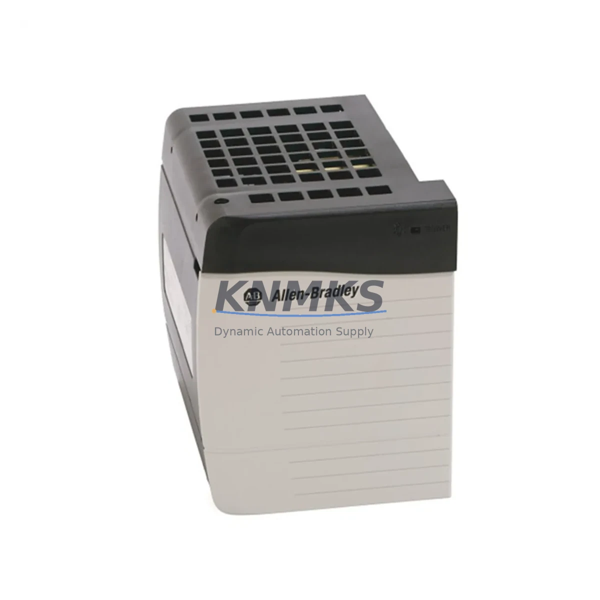
Allen-Bradley 1756-PA75 Migration-Ready AC Power Supply for ControlLogix Legacy Systems
The Allen-Bradley 1756-PA75 is a 75W AC input power supply module designed for the ControlLogix 1756 chassis platform. As legacy ControlLogix installations age and original power supply modules approach end-of-life, the 1756-PA75 serves as a direct, migration-ready replacement that preserves existing backplane architecture, program logic, and field wiring without requiring a full system redesign. Whether you are restoring a failed control cabinet, extending the service life of a 1756-L55 or 1756-L61 controller-based system, or executing a planned upgrade from an earlier ControlLogix generation, the 1756-PA75 delivers the power capacity and slot compatibility required for uninterrupted operation.
Rated for 85–265V AC input across 47–63 Hz, the 1756-PA75 supplies 5VDC backplane power to support a full range of 1756 I/O modules, communication modules, and controller cards within the same chassis. Its form factor is identical to earlier ControlLogix power supply variants, making it a drop-in mechanical fit for existing 1756-A4, 1756-A7, 1756-A10, 1756-A13, and 1756-A17 chassis sizes. Before installation, engineers should verify total backplane current draw across all installed modules — including analog I/O cards such as the 1756-IF16 or 1756-OF8, digital I/O modules, and any installed 1756-EN2T EtherNet/IP communication modules — to confirm the 75W budget is not exceeded.
Migration Compatibility Table
| Parameter | 1756-PA75 Specification | Migration Notes |
|---|---|---|
| Input Voltage | 85–265V AC, 47–63 Hz | Compatible with global AC supply; verify site voltage before installation |
| Output Power | 75W backplane power | Audit total module current draw before replacement; upgrade to 1756-PA75/B if margin is tight |
| Chassis Compatibility | All 1756-Axxx chassis (A4–A17) | Direct mechanical fit; no chassis modification required |
| Controller Compatibility | 1756-L5x, 1756-L6x, 1756-L7x series | Firmware version on controller does not affect PSU replacement; no re-flash required |
| Communication Modules | 1756-EN2T, 1756-CN2, 1756-DNB | EtherNet/IP, ControlNet, DeviceNet links remain active post-swap if chassis power is maintained via redundant PSU |
| Installation Space | Single slot, left-most chassis position | Confirm slot 0 is reserved; no adjacent module relocation needed |
| Firmware Compatibility | No firmware on PSU | No firmware update required; plug-and-play replacement |
| Replacement Path | Replaces 1756-PA72, 1756-PA75 (all series) | Series A/B/C variants are functionally interchangeable in most applications |
| Support terms | 12 Months | Covers manufacturing defects; includes pre-shipment functional test |
Retrofit Planning for Existing Automation Systems
Successful integration of the 1756-PA75 into a legacy control system requires a structured pre-retrofit assessment. Begin by documenting the existing chassis configuration: record every module installed in the 1756 chassis, its catalog number, and its 5V and 24V current consumption from the module’s technical datasheet. Sum the 5VDC loads across all slots — including the resident 1756-L61 or 1756-L71 controller, any 1756-EN2T EtherNet/IP bridge modules, 1756-IF16 analog input cards, and 1756-OB16E digital output modules — and confirm the total remains within the 75W envelope of the 1756-PA75.
For systems running ControlNet as the primary backplane communication medium via a 1756-CN2 module, verify that the ControlNet network schedule (SMAX/UMAX parameters) does not need to be re-commissioned after the power cycle caused by the PSU swap. In most cases, the network schedule is stored in the 1756-CN2 module’s non-volatile memory and survives a power interruption without loss. Similarly, any 1756-DNB DeviceNet scanner module retains its scanlist configuration in non-volatile memory, so DeviceNet field devices will resume normal operation once backplane power is restored.
If the existing installation uses a 1756-PSCA2 power supply chassis adapter for redundant power configurations, confirm that the second power supply slot is populated with a compatible unit before removing the primary 1756-PA75. Redundant PSU configurations allow hot-swap replacement without dropping backplane power, which is the preferred method for high-availability lines where stopping the process is not acceptable. For single-PSU chassis, coordinate the swap during a planned maintenance window and ensure the 1756-L7x controller’s program has been saved to the CompactFlash or SD card so that the application can be reloaded quickly if needed.
Terminal wiring on the 1756-PA75 is straightforward: L1, L2/N, and PE (ground) connections are made at the three-position terminal block on the front face of the module. Confirm wire gauge matches the site’s electrical code requirements and that the upstream circuit breaker rating is appropriate for the inrush current characteristic of the supply. No special tools or programming software are required for the physical installation.
Downtime Control During System Migration
Minimizing unplanned downtime during a power supply replacement on a live ControlLogix system begins with preparation, not speed. Before the maintenance window opens, use RSLogix 5000 or Studio 5000 Logix Designer to perform an online upload of the controller program and save a verified backup to both a local engineering workstation and a removable storage card seated in the controller. This ensures that even in the unlikely event of a controller memory loss during the power interruption, the application logic, tag database, HMI faceplates linked to the 1756-L6x or 1756-L7x controller, and motion axis configurations can be restored within minutes rather than hours.
During the swap itself, work systematically: de-energize the chassis by switching off the upstream breaker, wait for the PSU status LED to extinguish fully, then slide the 1756-PA75 out of slot 0. Insert the replacement unit, re-engage the chassis latch, restore AC power, and observe the PSU OK LED. The ControlLogix controller will execute its standard power-up diagnostic sequence and transition to RUN mode automatically if the keyswitch is in the RUN position. Verify all I/O module status LEDs return to their normal operating state and confirm that the SCADA or DCS supervisory system — which may be polling the controller via an OPC-UA or EtherNet/IP explicit messaging path — re-establishes its data connection within the expected timeout window.
For facilities where even a brief power interruption is unacceptable, a parallel migration strategy using a second chassis populated with a new 1756-PA75, a duplicate controller, and mirrored I/O wiring allows the new system to be commissioned and validated offline before a single-scan cutover is executed at the field terminal strips. This approach is particularly effective when the legacy system also includes aging 1756-IF16 analog input modules or 1756-OB16E output modules that are being replaced simultaneously as part of a broader control system life-extension project.
Every 1756-PA75 unit shipped from our inventory undergoes a pre-shipment functional test under load to verify output voltage regulation, inrush limiting, and status LED behavior before dispatch. Units are packaged in anti-static, shock-absorbing materials suitable for international freight. A support terms confirmed by quotation cover all manufacturing defects from the date of invoice.
Retrofit Support FAQ
Q: Is the 1756-PA75 a direct replacement for the 1756-PA72?
A: Yes. The 1756-PA75 is the higher-capacity successor to the 1756-PA72 and is mechanically and electrically compatible with all 1756-Axxx chassis. The increased 75W output rating provides additional headroom for chassis configurations that were operating near the 1756-PA72’s 72W limit. No wiring changes or software modifications are required.
Q: Will replacing the power supply affect the controller program or HMI configuration?
A: In a single-PSU chassis, replacing the 1756-PA75 requires a brief power interruption. The 1756-L6x and 1756-L7x controllers store the application program in non-volatile flash memory and will reload and resume execution automatically after power is restored. HMI screens connected via EtherNet/IP will re-establish their tag subscriptions once the controller returns to RUN mode. We recommend performing a program backup before any maintenance activity as a precaution.
Q: Do you provide pre-shipment testing and what does the support terms confirmed by quotation cover?
A: Yes. Every unit is functionally tested under load prior to shipment to verify correct output voltage, current limiting behavior, and status indicator operation. The support terms confirmed by quotation cover defects in materials and workmanship from the date of invoice. It does not cover damage resulting from incorrect installation, overvoltage events, or physical mishandling. Support requests are processed via our sales team at admin@knmks.com.
Q: What is the typical lead time and do you maintain stock?
A: We maintain ready stock of the 1756-PA75 to support urgent replacement and planned maintenance schedules. Standard orders are dispatched within 1–3 business days. For large-quantity orders or projects requiring multiple units across a site-wide ControlLogix upgrade, contact our team directly to confirm availability and arrange consolidated shipment.
© 2026 KNMKS. All rights reserved.
Original Source: https://knmks.com
Contact: admin@knmks.com | +86 18359268345
Product Identification
- Brand / Ecosystem
-
Allen-Bradley
Allen-Bradley - Model / Series
-
1756-PA75
ControlLogix Series - Product Family
- Power Supplies
- Availability Status
- Available on request after model and quantity confirmation
- Inquiry Type
- B2B RFQ, replacement inquiry and project spare-part request
- Pre-Quote Check
- Exact SKU, brand, series, quantity, nameplate photos and destination country are checked before quotation
System Path
Where this product fits in the KNMKS automation structure.
Specification & Inquiry Focus
- Power range
- DIN rail and switching power supplies
- Common needs
- Voltage, current and mounting style
- Project support
- Control cabinet and panel-builder inquiries
Buyer Confirmation
Information KNMKS checks before replying.
- Exact model
- 1756-PA75
- Brand / ecosystem
- Allen-Bradley
- Product family
- Power Supplies
- Application note
- Replacement, maintenance, project build or spare-part list
- Useful photos
- Nameplate, installed unit, cabinet layout or connector side
- Delivery details
- Quantity, destination country and target schedule
Document Support
Files and notes can be confirmed during quotation.
- Product photos or nameplate confirmation when available
- Packing and delivery notes before quotation confirmation
- Support scope and delivery terms confirmed per inquiry
- Export document coordination for qualified B2B requests
Inquiry Support
- 24VDC and cabinet power selection support
- Stable power support for PLC and HMI systems
- Batch inquiry support for panel builders
What to Send Us
- Brand and exact model number: Allen-Bradley 1756-PA75
- Quantity and required delivery time
- Application, replacement requirement or nameplate photo
- Destination country and shipping preference
RFQ Preparation
This is a product inquiry page built for RFQ communication.
Fast Model Check
Send this model to KNMKS for confirmation.
Include quantity, destination country and photos if this is a maintenance replacement. The inquiry will be saved with a reference number after submission.
Brand & Compatibility Note
KNMKS displays automation product information for well-known industrial brand ecosystems and compatible replacement references. Brand names are used for product identification and compatibility reference only; final availability and commercial terms are confirmed per quotation.
 Manufacturing
 Machine Tools
 Packaging
 Energy & Power
 PLCs & Controllers
 HMI & Displays
 Servo Systems
 Variable Frequency Drives