
Overview
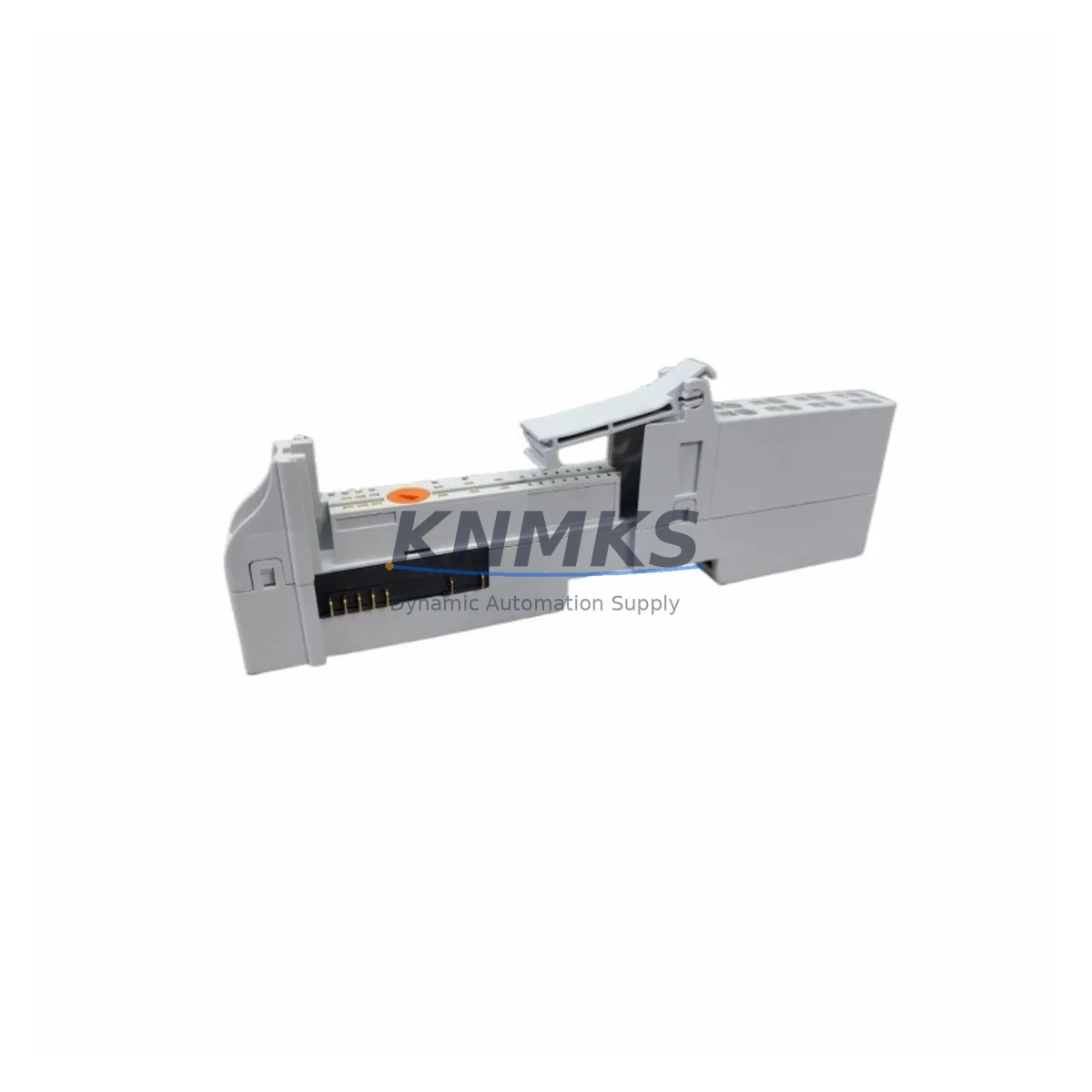
Allen-Bradley 1734-TBS Migration-Ready Terminal Base for Legacy Control Systems
When aging POINT I/O installations reach end-of-life or require expansion, the Allen-Bradley 1734-TBS screw-clamp terminal base delivers a proven, migration-ready foundation that preserves existing field wiring while enabling seamless module replacement. Designed for the 1734 POINT I/O platform, the 1734-TBS supports direct drop-in substitution for worn or discontinued terminal bases without requiring rewiring of field instrumentation — a critical advantage in continuous process environments where unplanned downtime carries significant operational cost.
The 1734-TBS accepts standard 1734 I/O modules including digital input, digital output, analog input, and analog output variants. During a retrofit, engineers must confirm that the replacement base matches the original wiring style — screw-clamp in this case — and verify that the module address assignment within the 1734-AENT or 1734-AENTR EtherNet/IP adapter remains consistent with the existing Logix program tag structure. Mismatched module addressing is one of the most common causes of post-replacement faults in POINT I/O systems, and pre-commissioning verification against the original I/O tree in Studio 5000 Logix Designer is strongly recommended before energizing the updated assembly.
Field teams replacing a 1734-TBS in an active control cabinet should also inspect the condition of the 1734-TOP or 1734-TOP3L wiring connector retained from the original base. In most retrofit scenarios, the connector transfers directly to the new base, preserving all field terminations and eliminating the need to re-terminate individual conductors. This approach significantly reduces commissioning time and minimizes the risk of wiring errors during the changeover window.
Migration Compatibility Table
| Parameter | Specification / Retrofit Guidance |
|---|---|
| SKU | 1734-TBS |
| Series | Allen-Bradley POINT I/O — 1734 Series |
| Terminal Style | Screw-Clamp (replaces 1734-TBS screw-type bases) |
| Compatible Modules | All standard 1734 POINT I/O digital and analog I/O modules |
| Adapter Compatibility | 1734-AENT, 1734-AENTR, 1734-PDN, 1734-ADN |
| Wiring Connector Transfer | 1734-TOP / 1734-TOP3L connector retained from original base |
| Module Address Verification | Required — confirm slot position in Studio 5000 Logix Designer |
| Installation Space | Standard 1734 DIN rail footprint — no panel modification required |
| Firmware Dependency | None — passive terminal base, no firmware required |
| Origin | United States |
| Support terms | support terms confirmed by quotation — covers manufacturing defects and functional failure |
Retrofit Planning for Existing Automation Systems
A successful 1734-TBS replacement begins well before the maintenance window opens. The first step is to export the current I/O configuration from the 1734-AENT or 1734-AENTR adapter using RSLinx Classic or Studio 5000, documenting each slot’s module type, address offset, and connection parameters. This baseline record becomes the reference for post-replacement verification and is essential if the Logix controller needs to be placed in program mode during the swap.
In installations where the 1734-TBS is part of a larger POINT I/O bank, the adjacent modules — including 1734-IB8 digital input modules, 1734-OB8 digital output modules, and 1734-IE2C analog current input modules — must remain undisturbed during the base replacement. The modular snap-together design of the 1734 platform allows individual bases to be removed and replaced without disassembling the entire bank, provided the DIN rail mounting screws are accessible and the wiring connector is carefully extracted before removal.
Power distribution within the POINT I/O bank is managed by the 1734-EP24DC power distribution module, which segments the bank into independently powered groups. Before replacing a 1734-TBS, confirm which power segment the target base belongs to and whether isolating that segment will affect adjacent modules still required for process control. In some installations, a temporary bypass using a portable 24 VDC supply connected to the field device can maintain sensor continuity while the base is exchanged.
For systems communicating over EtherNet/IP, the 1734-AENTR dual-port adapter supports Device Level Ring (DLR) topology, which provides network redundancy during maintenance activities. Enabling DLR before beginning the retrofit allows the network to reroute traffic automatically if a cable is disturbed, reducing the risk of communication loss to the CompactLogix or ControlLogix controller managing the process. After the replacement is complete, the adapter’s web interface should be used to verify that all modules have re-established connections and that no inhibited connections remain active in the Logix program.
Downtime Control During System Migration
Minimizing downtime during a 1734-TBS replacement requires a structured approach that separates preparation, execution, and verification into distinct phases. During preparation, the maintenance team should confirm that a tested replacement base is on hand, that the wiring connector is compatible, and that the Logix program has been backed up to a secure location. The controller should be placed in program mode only after confirming that all safety interlocks and process holds are active and that the field devices connected to the target base are in a safe state.
During execution, the wiring connector is extracted from the original base, the module is removed, the base is unclipped from the DIN rail, and the replacement base is installed in reverse order. The entire mechanical exchange typically takes under five minutes for an experienced technician. The critical time investment is in the pre- and post-replacement verification steps: confirming that the module seats correctly, that the connector is fully engaged, and that the adapter recognizes the module before the controller is returned to run mode.
Post-replacement, the Logix controller’s I/O tree should be inspected for any faulted connections, and the HMI display associated with the affected I/O points should be monitored for correct signal values before releasing the process back to automatic control. All replacement activities, including the date, technician name, module serial number, and post-replacement test results, should be recorded in the site maintenance log to support future audits and support requests.
KNMKS maintains verified stock of the 1734-TBS and related 1734 series components, with pre-shipment functional testing performed on every unit. Each module ships with a support terms confirmed by quotation covering manufacturing defects and functional failure, supporting long-term spare parts planning for facilities managing multiple POINT I/O installations across distributed sites.
Retrofit Support FAQ
Q: Is the 1734-TBS a direct drop-in replacement for existing screw-clamp terminal bases in a 1734 POINT I/O bank?
A: Yes. The 1734-TBS is dimensionally and electrically compatible with existing 1734 screw-clamp terminal bases. The 1734-TOP wiring connector transfers directly from the original base, preserving all field terminations. No rewiring is required in standard replacement scenarios.
Q: Does replacing a 1734-TBS require changes to the Logix program or I/O configuration?
A: Not if the replacement base is installed in the same slot position with the same module type. The Logix program references module tags by slot address, so maintaining the original slot position ensures program compatibility. If the slot position changes, the I/O tree in Studio 5000 must be updated and the program re-downloaded.
Q: What pre-shipment testing is performed on the 1734-TBS before delivery?
A: Every 1734-TBS unit supplied by KNMKS undergoes functional verification prior to shipment, including mechanical inspection of the DIN rail clip, connector engagement check, and continuity verification of the terminal block. Units that do not meet specification are quarantined and not shipped.
Q: What support terms and long-term supply support does KNMKS provide for the 1734-TBS?
A: KNMKS provides a support terms confirmed by quotation on all 1734-TBS units covering manufacturing defects and functional failure from the date of shipment. Long-term supply agreements are available for facilities requiring guaranteed stock over 12 to 36-month planning horizons. Contact admin@knmks.com for volume pricing and supply commitment terms.
© 2026 KNMKS. All rights reserved.
Original Source: https://knmks.com
Contact: admin@knmks.com | +86 18359268345
Product Identification
- Brand / Ecosystem
-
Allen-Bradley
Allen-Bradley - Model / Series
- 1734-TBS
- Product Family
- PLCs & Controllers
- Availability Status
- Available on request after model and quantity confirmation
- Inquiry Type
- B2B RFQ, replacement inquiry and project spare-part request
- Pre-Quote Check
- Exact SKU, brand, series, quantity, nameplate photos and destination country are checked before quotation
System Path
Where this product fits in the KNMKS automation structure.
Specification & Inquiry Focus
- Control platform
- PLC, PAC and modular controllers
- Common needs
- CPU, rack, power and I/O expansion
- Project support
- Replacement, cabinet build and maintenance
Buyer Confirmation
Information KNMKS checks before replying.
- Exact model
- 1734-TBS
- Brand / ecosystem
- Allen-Bradley
- Product family
- PLCs & Controllers
- Application note
- Replacement, maintenance, project build or spare-part list
- Useful photos
- Nameplate, installed unit, cabinet layout or connector side
- Delivery details
- Quantity, destination country and target schedule
Document Support
Files and notes can be confirmed during quotation.
- Product photos or nameplate confirmation when available
- Packing and delivery notes before quotation confirmation
- Support scope and delivery terms confirmed per inquiry
- Export document coordination for qualified B2B requests
Inquiry Support
- Model cross-checking before quotation
- CPU, power, rack and expansion module matching
- Support for replacement and project inquiry
What to Send Us
- Brand and exact model number: Allen-Bradley 1734-TBS
- Quantity and required delivery time
- Application, replacement requirement or nameplate photo
- Destination country and shipping preference
RFQ Preparation
This is a product inquiry page built for RFQ communication.
Fast Model Check
Send this model to KNMKS for confirmation.
Include quantity, destination country and photos if this is a maintenance replacement. The inquiry will be saved with a reference number after submission.
Brand & Compatibility Note
KNMKS displays automation product information for well-known industrial brand ecosystems and compatible replacement references. Brand names are used for product identification and compatibility reference only; final availability and commercial terms are confirmed per quotation.
 Manufacturing
 Machine Tools
 Packaging
 Energy & Power
 HMI & Displays
 Servo Systems
 Variable Frequency Drives
 Sensors