
Overview
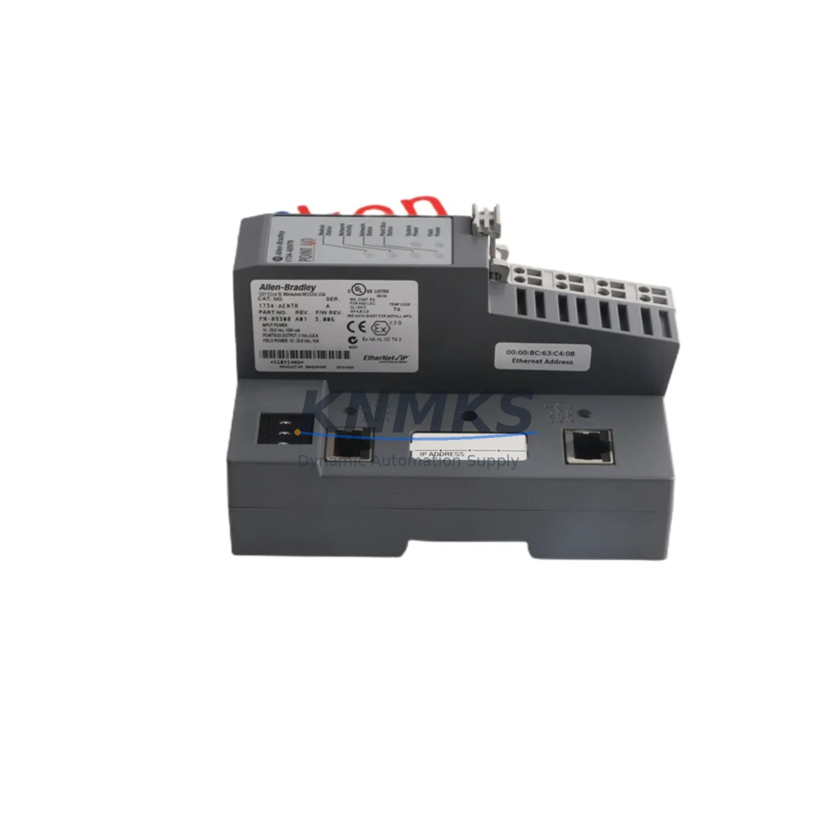
Allen-Bradley 1734-AENT Spare Part for Factory Uptime
The Allen-Bradley 1734-AENT is a POINT I/O EtherNet/IP Network Adapter designed for distributed I/O applications in demanding industrial environments. As a maintenance-proven spare part, the 1734-AENT enables rapid restoration of EtherNet/IP communication links in control cabinets, reducing unplanned downtime and supporting continuous production across petrochemical, automotive, food & beverage, water treatment, and discrete manufacturing facilities.
Maintenance engineers and procurement teams managing aging Rockwell Automation systems rely on verified, stock-backed 1734-AENT units to sustain POINT I/O architectures without costly platform migrations. Whether you are executing a scheduled annual overhaul, responding to a communication fault alarm, or building a strategic spare parts inventory for a multi-site facility, the 1734-AENT is a critical node in your EtherNet/IP topology that demands pre-tested, support terms-backed sourcing.
Each unit shipped from KNMKS undergoes pre-shipment functional verification, ensuring the adapter initializes correctly, establishes EtherNet/IP connections, and passes basic I/O communication checks before leaving our facility. A support terms confirmed by quotation cover all units, providing procurement engineers with the confidence needed for long-cycle maintenance planning and capital spares budgeting.
Spare Maintenance Table
| SKU / Part Number | 1734-AENT |
| Brand / Manufacturer | Allen-Bradley (Rockwell Automation) |
| Series | POINT I/O 1734 Series |
| Product Type | EtherNet/IP Network Adapter |
| Communication Protocol | EtherNet/IP (CIP over Ethernet) |
| Supply Voltage | 24V DC (via POINT I/O power supply) |
| I/O Capacity | Up to 63 POINT I/O modules per adapter |
| Network Ports | Single RJ-45 EtherNet/IP port |
| IP Rating | IP20 (panel/cabinet mount) |
| Operating Temperature | 0°C to 55°C |
| Mounting | DIN rail, POINT I/O base unit |
| Compatibility | 1734 POINT I/O modules, ControlLogix, CompactLogix, Studio 5000 |
| Country of Origin | United States |
| Pre-Shipment Testing | Yes — functional communication verification |
| Support terms | 12 Months |
| Typical Application | Distributed I/O, machine control, process automation, cabinet integration |
| Maintenance Category | Critical Communication Infrastructure — recommend 1 unit minimum on-site spare |
Maintenance Planning for Continuous Operation
When replacing or inspecting the 1734-AENT in a live control cabinet, a thorough maintenance workflow extends beyond the adapter itself. The 1734-AENT sits at the heart of the POINT I/O communication backbone, and its failure typically triggers cascading I/O faults across the entire adapter segment. Maintenance engineers should treat a 1734-AENT replacement as an opportunity to audit the surrounding electrical and communication infrastructure.
Power Supply Verification: Confirm the POINT I/O power supply module — commonly a 1734-EP24DC or equivalent 24V DC power supply — is delivering stable voltage within specification. Voltage sags or ripple on the 24V rail are a leading cause of premature adapter resets and communication timeouts. Inspect the power supply’s output terminals and check for signs of thermal stress or connector oxidation.
I/O Module Integrity: After restoring the adapter, cycle through all downstream 1734-series I/O modules — including digital input modules such as the 1734-IB8, digital output modules, and analog signal modules — to confirm each module is recognized and reporting correctly in Studio 5000 or RSLogix 5000. A faulty I/O module can mask itself as an adapter communication error.
EtherNet/IP Network Infrastructure: Inspect the Ethernet patch cable connecting the 1734-AENT to the managed switch or ControlLogix backplane. Industrial-grade Cat5e or Cat6 cables with shielded connectors are recommended in high-EMI environments. Verify the managed switch port configuration — duplex mismatch and auto-negotiation failures are common causes of intermittent EtherNet/IP faults that are misdiagnosed as adapter hardware failures.
ControlLogix or CompactLogix Controller: Confirm the upstream ControlLogix 1756 or CompactLogix 5370/5380 controller firmware is compatible with the replacement 1734-AENT firmware revision. Mismatched firmware can prevent the adapter from being recognized in the I/O tree. Update the controller project’s I/O configuration if the replacement unit carries a different hardware revision.
Terminal Blocks and Field Wiring: Inspect the field-side terminal blocks connected to downstream I/O modules. Loose or corroded terminals on 1734-TB or 1734-TBS terminal bases are a frequent source of intermittent field signal faults that appear after an adapter replacement. Torque all terminals to specification and apply contact protection spray in humid or corrosive environments.
Signal Isolation and Protection: For analog I/O channels connected to field transmitters, verify that signal isolators or surge protection devices — such as those in the Phoenix Contact MINI Analog series or equivalent — are intact and not degraded. A failed isolator can introduce ground loops that corrupt analog readings and trigger nuisance alarms after a successful adapter replacement.
Building a cabinet-level spare parts kit that includes the 1734-AENT alongside a spare power supply module, a set of critical I/O modules, and a pre-configured Ethernet patch cable reduces mean time to repair (MTTR) from hours to minutes during emergency callouts.
Site Replacement Workflow
Step 1 — Pre-Replacement Documentation: Before removing the existing 1734-AENT, capture the current IP address, subnet mask, gateway, and EtherNet/IP node configuration from the adapter’s web interface or from the Studio 5000 project. Photograph the wiring and module arrangement on the DIN rail segment.
Step 2 — Safe Isolation: Place the upstream controller in Program mode to inhibit I/O outputs. Isolate the 24V DC power feed to the POINT I/O segment using the appropriate circuit breaker or fused disconnect. Verify zero voltage with a calibrated multimeter before handling the adapter.
Step 3 — Module Removal: Release the 1734-AENT from the DIN rail mounting base. Note the orientation of the power jumper (left-side power feed) and remove the module without disturbing adjacent I/O modules on the rail.
Step 4 — Replacement Unit Preparation: Configure the replacement 1734-AENT with the documented IP address and network settings using the adapter’s rotary switches or via BOOTP/DHCP assignment. Confirm the firmware revision matches or is compatible with the controller project.
Step 5 — Installation and Power-Up: Seat the replacement adapter on the DIN rail base, restore the 24V DC power feed, and observe the adapter’s status LEDs. A solid green NET LED and MOD LED indicate successful EtherNet/IP connection and module health. A flashing red LED indicates a configuration or network fault requiring further diagnosis.
Step 6 — Controller Reconnection and Verification: Return the controller to Run mode. Verify all I/O modules in the 1734-AENT segment are online and fault-free in the Studio 5000 I/O tree. Confirm field signals are reading correctly and that no inhibited connections remain active.
Step 7 — Documentation Update: Record the replacement date, unit serial number, firmware revision, and technician name in the site maintenance log. Update the spare parts inventory to trigger reorder of a replacement 1734-AENT unit, maintaining minimum stock levels for the site.
Spare Parts Support FAQ
Q1: Is the 1734-AENT compatible with both ControlLogix and CompactLogix systems?
Yes. The 1734-AENT is compatible with any EtherNet/IP scanner, including ControlLogix 1756-EN2T, CompactLogix 5370 and 5380 controllers, and third-party EtherNet/IP masters that support CIP connections. Compatibility is determined by the controller’s EtherNet/IP scanner capacity and the Studio 5000 or RSLogix 5000 project configuration, not by the adapter hardware revision alone.
Q2: How do you verify the 1734-AENT before shipment?
Each 1734-AENT unit is powered up and tested for EtherNet/IP communication initialization, LED status verification, and basic I/O module recognition before shipment. Units that fail any stage of pre-shipment testing are quarantined and not shipped. A test record is available upon request for critical procurement applications.
Q3: What is the support terms coverage and what does it include?
All 1734-AENT units supplied by KNMKS carry a support terms confirmed by quotation from the date of shipment. The support terms covers hardware defects, communication failures attributable to the adapter, and premature component failure under normal operating conditions. It does not cover damage caused by incorrect installation, overvoltage events, or physical impact. Support requests are processed with priority turnaround to minimize site downtime.
Q4: Can KNMKS support long-term or blanket purchase orders for 1734-AENT spares?
Yes. KNMKS supports long-term supply agreements, blanket purchase orders, and scheduled delivery programs for the 1734-AENT and related POINT I/O components. For multi-site facilities or OEM integrators requiring guaranteed stock availability over 12–36 month horizons, contact our sales team to discuss inventory reservation and priority allocation arrangements.
© 2026 KNMKS. All rights reserved.
Original Source: https://knmks.com
Contact: admin@knmks.com | +86 18359268345
Product Identification
- Brand / Ecosystem
-
Allen-Bradley
Allen-Bradley - Model / Series
- 1734-AENT
- Product Family
- PLCs & Controllers
- Availability Status
- Available on request after model and quantity confirmation
- Inquiry Type
- B2B RFQ, replacement inquiry and project spare-part request
- Pre-Quote Check
- Exact SKU, brand, series, quantity, nameplate photos and destination country are checked before quotation
System Path
Where this product fits in the KNMKS automation structure.
Specification & Inquiry Focus
- Control platform
- PLC, PAC and modular controllers
- Common needs
- CPU, rack, power and I/O expansion
- Project support
- Replacement, cabinet build and maintenance
Buyer Confirmation
Information KNMKS checks before replying.
- Exact model
- 1734-AENT
- Brand / ecosystem
- Allen-Bradley
- Product family
- PLCs & Controllers
- Application note
- Replacement, maintenance, project build or spare-part list
- Useful photos
- Nameplate, installed unit, cabinet layout or connector side
- Delivery details
- Quantity, destination country and target schedule
Document Support
Files and notes can be confirmed during quotation.
- Product photos or nameplate confirmation when available
- Packing and delivery notes before quotation confirmation
- Support scope and delivery terms confirmed per inquiry
- Export document coordination for qualified B2B requests
Inquiry Support
- Model cross-checking before quotation
- CPU, power, rack and expansion module matching
- Support for replacement and project inquiry
What to Send Us
- Brand and exact model number: Allen-Bradley 1734-AENT
- Quantity and required delivery time
- Application, replacement requirement or nameplate photo
- Destination country and shipping preference
RFQ Preparation
This is a product inquiry page built for RFQ communication.
Fast Model Check
Send this model to KNMKS for confirmation.
Include quantity, destination country and photos if this is a maintenance replacement. The inquiry will be saved with a reference number after submission.
Brand & Compatibility Note
KNMKS displays automation product information for well-known industrial brand ecosystems and compatible replacement references. Brand names are used for product identification and compatibility reference only; final availability and commercial terms are confirmed per quotation.
 Manufacturing
 Machine Tools
 Packaging
 Energy & Power
 HMI & Displays
 Servo Systems
 Variable Frequency Drives
 Sensors