
Overview
Allen-Bradley 1715-TASIB16D Migration-Ready Digital Input Assembly: Legacy System Migration and Compatible Upgrade
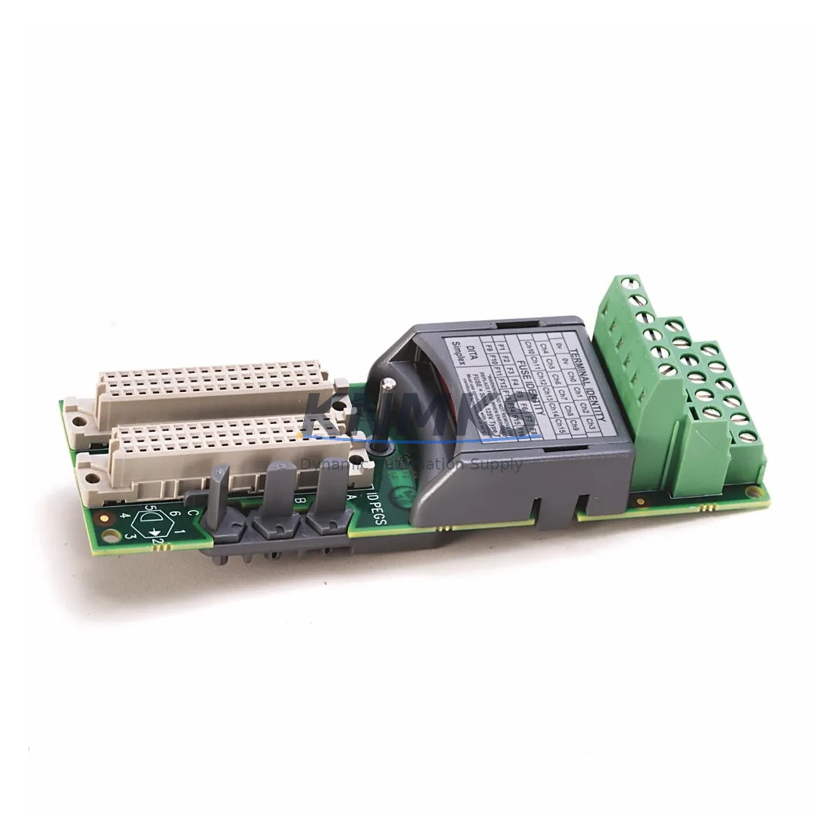
The Allen-Bradley 1715-TASIB16D is a 16-channel digital input termination assembly designed for the 1715 Redundant I/O platform — one of Rockwell Automation’s most widely deployed safety-rated, redundant control architectures in process industries including oil & gas, chemical, power generation, and water treatment. As legacy 1715 systems approach end-of-life and spare parts become increasingly scarce, the 1715-TASIB16D remains a critical component for both ongoing maintenance and structured migration projects.
This termination assembly interfaces directly with the 1715-IB16D 16-channel digital input module, providing the field-side wiring termination point for 24V DC discrete input signals. Its role in the redundant I/O architecture means that any replacement or upgrade must be carefully validated against the existing backplane configuration, module addressing scheme, and redundancy controller firmware version. When sourcing a replacement 1715-TASIB16D, engineers must confirm that the termination assembly revision level is compatible with the installed 1715-IB16D module revision and the 1715-AENTR adapter firmware currently running in the chassis.
In retrofit and modernization projects, the 1715-TASIB16D is frequently encountered alongside the 1715-A4 four-slot chassis and the 1715-A2 two-slot chassis. These chassis form the physical backbone of the redundant I/O drop, and any termination assembly replacement must account for available slot positions, backplane connector alignment, and DIN rail or panel mounting clearances. Field engineers should measure available cabinet depth and verify that the replacement assembly’s physical envelope matches the original installation before scheduling a maintenance window.
Migration Compatibility Table
| Parameter | 1715-TASIB16D Specification | Migration / Retrofit Notes |
|---|---|---|
| Compatible Input Module | 1715-IB16D (16-Ch 24V DC Digital Input) | Verify module revision matches termination assembly revision |
| Chassis Compatibility | 1715-A4, 1715-A2 | Confirm slot availability and backplane connector seating |
| Communication Adapter | 1715-AENTR (EtherNet/IP Dual-Port) | Firmware version must support installed I/O module revision |
| Signal Voltage | 24V DC Discrete Input | Verify field wiring voltage; no rewiring required for like-for-like swap |
| Terminal Wiring | Screw-type field terminals | Document existing terminal assignments before removal; re-terminate per original drawing |
| Module Addressing | Slot-based, configured in Studio 5000 | No address change required for direct replacement; verify I/O tree in controller project |
| Redundancy Mode | Supports 1715 Redundant I/O architecture | Both primary and secondary assemblies must be replaced if upgrading redundant pair |
| Installation Space | Standard 1715 chassis slot footprint | Confirm cabinet depth ≥ 200mm; DIN rail or panel mount |
| Firmware Compatibility | Validated with 1715-AENTR firmware v3.x and above | Update adapter firmware before hot-swap if running legacy firmware |
| Support terms | support terms confirmed by quotation — covers manufacturing defects; includes pre-shipment functional verification | |
Retrofit Planning for Existing Automation Systems
Successful integration of the 1715-TASIB16D into an existing or upgraded control system requires a structured pre-replacement audit. Before scheduling a maintenance window, the responsible engineer should pull the current Studio 5000 project file and review the I/O configuration tree to confirm that the 1715-IB16D module is mapped correctly and that no custom module definitions (CMDs) have been applied that could affect the replacement assembly’s recognition by the controller.
Power budget verification is a mandatory step. The 1715 Redundant I/O system draws backplane power from the 1715-AENTR adapter, and adding or replacing termination assemblies can affect the total current draw on the 24V DC backplane supply. Engineers should calculate the aggregate current consumption of all installed modules — including any 1715-OB16D digital output modules, 1715-IF16 analog input modules, or 1715-OF8I analog output modules sharing the same chassis — and confirm that the system power supply has sufficient headroom.
For sites where the 1715 system communicates upstream to a ControlLogix or CompactLogix controller via EtherNet/IP, the 1715-AENTR adapter’s IP address, subnet mask, and connection parameters should be documented before any hardware change. If the replacement 1715-TASIB16D is installed as part of a broader migration from an older 1771 or 1746 I/O platform, the project team must also account for differences in signal scaling, filter time constants, and diagnostic data formats between the legacy and current platforms. In such cases, a signal isolation module or marshalling panel may be required to bridge legacy field wiring to the new termination assembly’s terminal block layout.
Cabinet space planning is equally important. The 1715-TASIB16D occupies a defined slot in the 1715 chassis, but the associated field wiring conduit, cable tray routing, and terminal block labeling must all be reviewed. If the retrofit is part of a control cabinet upgrade that also involves replacing the 1715-AENTR adapter or expanding the chassis from a 1715-A2 to a 1715-A4, the physical layout of the cabinet interior will change, and cable lengths may need to be adjusted accordingly.
Downtime Control During System Migration
Minimizing unplanned downtime is the primary operational concern when replacing a termination assembly in a live redundant I/O system. The 1715 Redundant I/O architecture is specifically designed to support online module replacement under certain conditions, but this capability depends on the controller’s redundancy configuration and the current health status of both the primary and secondary I/O paths.
Before initiating the physical swap, the control system engineer should place the affected I/O drop into a known safe state — typically by inhibiting the module in Studio 5000 and confirming that the process logic has transitioned to a safe hold condition. For continuous process applications, this may require coordination with the operations team to temporarily hold the affected process loop in manual mode at the DCS or HMI level. If the site uses a FactoryTalk View SE or FactoryTalk View ME HMI, the relevant faceplates should be reviewed to confirm that manual override capability is available and that alarm suppression is in place for the duration of the swap.
Once the replacement 1715-TASIB16D is physically installed and field wiring is re-terminated per the original as-built drawings, the module should be re-enabled in Studio 5000 and the I/O connection status verified in the controller’s I/O tree. A point-by-point functional check of all 16 input channels should be performed before returning the loop to automatic control. This check should include both the primary and secondary I/O paths if the system is configured for redundant operation. Total planned downtime for a like-for-like replacement, assuming pre-staged hardware and a prepared engineering team, is typically 30 to 90 minutes per assembly.
For sites where zero-downtime replacement is required, the recommended approach is to pre-configure the replacement assembly offline, verify its compatibility with the installed firmware and module revision, and coordinate the swap during a scheduled process hold or turnaround window. Shipping lead times should be factored into the maintenance schedule, and a verified spare should be held in the site’s critical spares inventory to avoid unplanned production loss.
Retrofit Support FAQ
Q1: Is the 1715-TASIB16D a direct drop-in replacement for the original assembly in my 1715 Redundant I/O chassis?
Yes, for like-for-like replacements within the same 1715 chassis generation. The assembly uses the same backplane connector, slot footprint, and field terminal layout as the original. No changes to the Studio 5000 project file or module addressing are required for a direct replacement, provided the replacement assembly revision is compatible with the installed 1715-IB16D module revision.
Q2: What pre-shipment testing is performed on the 1715-TASIB16D before delivery?
Each unit undergoes functional verification prior to shipment, including backplane connector integrity checks and visual inspection for physical damage. Units are shipped in anti-static packaging with revision labels intact. A support terms confirmed by quotation cover manufacturing defects from the date of shipment.
Q3: Can the 1715-TASIB16D be used in a migration from a legacy 1771 or 1746 I/O system?
The 1715-TASIB16D is designed exclusively for the 1715 Redundant I/O platform and is not directly interchangeable with 1771 or 1746 I/O termination hardware. However, it is commonly used as the target termination assembly in migration projects where legacy 1771 or 1746 field wiring is being re-terminated to the 1715 platform. In these cases, a marshalling panel or signal conditioning module is typically used to bridge the legacy wiring to the new terminal block layout.
Q4: What is the typical lead time and stock availability for the 1715-TASIB16D?
We maintain in-stock inventory of the 1715-TASIB16D to support urgent maintenance and retrofit requirements. Standard orders ship within 1–3 business days. For large-quantity project orders or scheduled turnaround supply, please contact our sales team to confirm availability and arrange a dedicated allocation.
© 2026 KNMKS. All rights reserved.
Original Source: https://knmks.com
Contact: admin@knmks.com | +86 18359268345
Product Identification
- Brand / Ecosystem
-
Allen-Bradley
Allen-Bradley - Model / Series
- 1715-TASIB16D
- Product Family
- PLCs & Controllers
- Availability Status
- Available on request after model and quantity confirmation
- Inquiry Type
- B2B RFQ, replacement inquiry and project spare-part request
- Pre-Quote Check
- Exact SKU, brand, series, quantity, nameplate photos and destination country are checked before quotation
System Path
Where this product fits in the KNMKS automation structure.
Specification & Inquiry Focus
- Control platform
- PLC, PAC and modular controllers
- Common needs
- CPU, rack, power and I/O expansion
- Project support
- Replacement, cabinet build and maintenance
Buyer Confirmation
Information KNMKS checks before replying.
- Exact model
- 1715-TASIB16D
- Brand / ecosystem
- Allen-Bradley
- Product family
- PLCs & Controllers
- Application note
- Replacement, maintenance, project build or spare-part list
- Useful photos
- Nameplate, installed unit, cabinet layout or connector side
- Delivery details
- Quantity, destination country and target schedule
Document Support
Files and notes can be confirmed during quotation.
- Product photos or nameplate confirmation when available
- Packing and delivery notes before quotation confirmation
- Support scope and delivery terms confirmed per inquiry
- Export document coordination for qualified B2B requests
Inquiry Support
- Model cross-checking before quotation
- CPU, power, rack and expansion module matching
- Support for replacement and project inquiry
What to Send Us
- Brand and exact model number: Allen-Bradley 1715-TASIB16D
- Quantity and required delivery time
- Application, replacement requirement or nameplate photo
- Destination country and shipping preference
RFQ Preparation
This is a product inquiry page built for RFQ communication.
Fast Model Check
Send this model to KNMKS for confirmation.
Include quantity, destination country and photos if this is a maintenance replacement. The inquiry will be saved with a reference number after submission.
Brand & Compatibility Note
KNMKS displays automation product information for well-known industrial brand ecosystems and compatible replacement references. Brand names are used for product identification and compatibility reference only; final availability and commercial terms are confirmed per quotation.
 Manufacturing
 Machine Tools
 Packaging
 Energy & Power
 HMI & Displays
 Servo Systems
 Variable Frequency Drives
 Sensors