
Overview
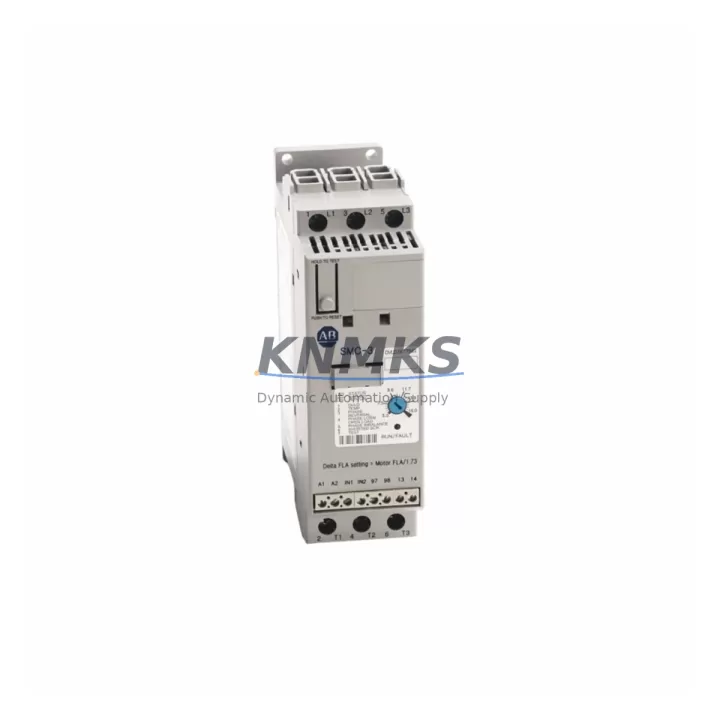
Allen-Bradley 150-C25NBR Migration-Ready Soft Starter: Legacy System Retrofit & Upgrade
The Allen-Bradley 150-C25NBR is a 25A SMC-3 series soft starter engineered for seamless integration into existing motor control centers (MCCs), legacy control cabinets, and aging automation systems. As original SMC-3 units approach end-of-life or become increasingly difficult to source through standard distribution channels, the 150-C25NBR serves as a verified migration-ready replacement that preserves existing wiring configurations, terminal layouts, and control logic without requiring panel redesign or PLC reprogramming.
For maintenance engineers and system integrators managing long-lifecycle installations — particularly those built around Allen-Bradley SLC 500, MicroLogix 1100, or PLC-5 control platforms — the 150-C25NBR provides a reliable path to extend operational continuity. Its compact DIN-rail and panel-mount footprint fits standard MCC bucket dimensions, and its 3-wire control interface is directly compatible with legacy hardwired start/stop circuits. Before installation, engineers should verify supply voltage (200–480V AC, 3-phase), confirm motor FLA against the 25A rated current, and check that existing overload relay settings align with the new unit’s trip class parameters.
Terminal wiring compatibility is a critical checkpoint during any soft starter swap. The 150-C25NBR uses standard L1/L2/L3 line-side and T1/T2/T3 load-side terminals consistent with earlier SMC-3 variants. Control terminals A1/A2 for coil voltage and the auxiliary contact block remain positionally consistent, reducing rewiring time during planned maintenance windows. If the existing installation uses a bypass contactor — common in legacy designs using the 100-C series contactors — the bypass logic and interlock wiring should be validated against the new unit’s auxiliary output ratings before energization.
Migration Compatibility Table
| Parameter | 150-C25NBR Specification | Retrofit / Migration Note |
|---|---|---|
| Rated Current | 25A | Verify motor FLA ≤ 25A; check existing overload settings |
| Supply Voltage | 200–480V AC, 3-Phase, 50/60Hz | Confirm panel voltage before installation; no transformer required for standard 480V systems |
| Control Voltage | 100–240V AC (A1/A2) | Compatible with legacy 120V AC control circuits; verify coil voltage at existing terminal block |
| Mounting | Panel mount / DIN rail | Fits standard MCC bucket; confirm cutout dimensions match existing enclosure |
| Communication | Standalone (hardwired); optional DeviceNet via 150-SM2 | For DeviceNet-integrated systems, retain existing 150-SM2 communication module if present |
| Bypass Contactor | Compatible with 100-C series | Validate interlock wiring and auxiliary contact ratings before energization |
| Firmware / Programming | Parameter-set via front panel or 193-DNENCAT | Document existing ramp time, current limit, and kick-start settings before replacement |
| Installation Space | Standard SMC-3 footprint | No panel modification required for like-for-like replacement |
| Support terms | 12 Months | Covered from date of shipment; includes functional test documentation |
Retrofit Planning for Existing Automation Systems
Successful integration of the 150-C25NBR into a legacy automation environment requires a structured pre-installation audit. Begin by documenting the existing soft starter’s parameter settings — ramp-up time, current limit percentage, kick-start voltage, and stop mode — using the original commissioning records or by reading values directly from the unit before removal. These parameters must be replicated on the replacement unit to maintain process continuity.
In systems where the SMC-3 is networked via a 150-SM2 DeviceNet communication module, the module can typically be retained and transferred to the replacement unit, preserving the existing node address and I/O mapping within the RSLogix 5000 or RSLogix 500 program. This eliminates the need to modify PLC ladder logic or update HMI faceplates configured in FactoryTalk View or PanelView terminals. If the installation includes a 1756-DNB or 1747-SDN DeviceNet scanner card, no scanner reconfiguration is required provided the node address is preserved.
For control cabinets that also house a 1606-XLP power supply module, verify that the 24V DC auxiliary circuit supplying the soft starter’s control board remains within voltage tolerance during motor starting transients. In multi-drive panels where several SMC-3 units share a common 1492-FB terminal block assembly, confirm that the replacement unit’s terminal pitch matches the existing feed-through block spacing to avoid rewiring the entire terminal strip.
Where the legacy system includes a 22-HIM-A3 remote HMI module or a 20-HIM-C6S operator interface panel, no HMI screen modifications are required for a like-for-like soft starter replacement. However, if the upgrade path involves migrating from a standalone SMC-3 to a networked configuration, HMI tag databases and alarm setpoints should be reviewed and updated accordingly. Signal isolators — such as those used to condition 4–20mA motor current feedback signals — should also be verified for compatibility with the new unit’s analog output specifications.
Downtime Control During System Migration
Minimizing unplanned downtime is the primary concern during any soft starter replacement in a live production environment. A structured hot-swap protocol begins with a full parameter backup of the existing 150-C25NBR (or predecessor unit), followed by pre-configuration of the replacement unit on the bench before the maintenance window opens. This approach reduces in-panel commissioning time to terminal reconnection and functional verification only.
Where process continuity is critical — such as in pump stations, compressor skids, or conveyor systems — consider staging the replacement during a scheduled preventive maintenance interval rather than responding reactively to a unit failure. Pre-positioning a tested and configured spare 150-C25NBR at the site ensures that mean time to repair (MTTR) is limited to physical swap time rather than procurement lead time.
During the swap, protect existing PLC program logic by placing the relevant output rung in a forced-off state rather than modifying the program file. This preserves the original ladder logic and allows immediate restoration of automatic control once the replacement unit passes functional verification. After energization, confirm motor acceleration profile, verify that the bypass contactor (if present) closes correctly at end-of-ramp, and check that all fault and status outputs are correctly mapped to the control system. A full-load test run under supervised conditions completes the commissioning process before returning the system to automatic operation.
Retrofit Support FAQ
Q: Is the 150-C25NBR a direct drop-in replacement for earlier SMC-3 units with the same current rating?
A: Yes. The 150-C25NBR maintains the same terminal layout, mounting footprint, and control interface as earlier SMC-3 variants at the 25A rating. Parameter settings must be manually transferred from the outgoing unit. Verify firmware revision compatibility if a 150-SM2 communication module is in use.
Q: Can the existing DeviceNet wiring and node address be retained during replacement?
A: In most cases, yes. If the 150-SM2 module is physically transferred to the replacement unit and the node address is preserved, the DeviceNet network configuration and PLC I/O mapping remain intact. No changes to the 1756-DNB or 1747-SDN scanner configuration are required.
Q: What pre-shipment testing is performed on the 150-C25NBR?
A: Each unit undergoes functional verification prior to shipment, including power-on self-test, control terminal continuity check, and parameter default confirmation. A test report is available upon request. Units are shipped in original or equivalent protective packaging to prevent transit damage.
Q: What support terms coverage applies, and what does it include?
A: All 150-C25NBR units supplied by KNMKS carry a support terms confirmed by quotation from the date of shipment. Coverage includes manufacturing defects and functional failures under normal operating conditions. Support requests are supported by our technical team with replacement dispatch typically within 3–5 business days of confirmed fault diagnosis.
© 2026 KNMKS. All rights reserved.
Original Source: https://knmks.com
Contact: admin@knmks.com | +86 18359268345
Product Identification
- Brand / Ecosystem
-
Allen-Bradley
Allen-Bradley - Model / Series
-
150-C25NBR
Assorted Series - Product Family
- PLCs & Controllers
- Availability Status
- Available on request after model and quantity confirmation
- Inquiry Type
- B2B RFQ, replacement inquiry and project spare-part request
- Pre-Quote Check
- Exact SKU, brand, series, quantity, nameplate photos and destination country are checked before quotation
System Path
Where this product fits in the KNMKS automation structure.
Specification & Inquiry Focus
- Control platform
- PLC, PAC and modular controllers
- Common needs
- CPU, rack, power and I/O expansion
- Project support
- Replacement, cabinet build and maintenance
Buyer Confirmation
Information KNMKS checks before replying.
- Exact model
- 150-C25NBR
- Brand / ecosystem
- Allen-Bradley
- Product family
- PLCs & Controllers
- Application note
- Replacement, maintenance, project build or spare-part list
- Useful photos
- Nameplate, installed unit, cabinet layout or connector side
- Delivery details
- Quantity, destination country and target schedule
Document Support
Files and notes can be confirmed during quotation.
- Product photos or nameplate confirmation when available
- Packing and delivery notes before quotation confirmation
- Support scope and delivery terms confirmed per inquiry
- Export document coordination for qualified B2B requests
Inquiry Support
- Model cross-checking before quotation
- CPU, power, rack and expansion module matching
- Support for replacement and project inquiry
What to Send Us
- Brand and exact model number: Allen-Bradley 150-C25NBR
- Quantity and required delivery time
- Application, replacement requirement or nameplate photo
- Destination country and shipping preference
RFQ Preparation
This is a product inquiry page built for RFQ communication.
Fast Model Check
Send this model to KNMKS for confirmation.
Include quantity, destination country and photos if this is a maintenance replacement. The inquiry will be saved with a reference number after submission.
Brand & Compatibility Note
KNMKS displays automation product information for well-known industrial brand ecosystems and compatible replacement references. Brand names are used for product identification and compatibility reference only; final availability and commercial terms are confirmed per quotation.
 Manufacturing
 Machine Tools
 Packaging
 Energy & Power
 HMI & Displays
 Servo Systems
 Variable Frequency Drives
 Sensors