
Overview
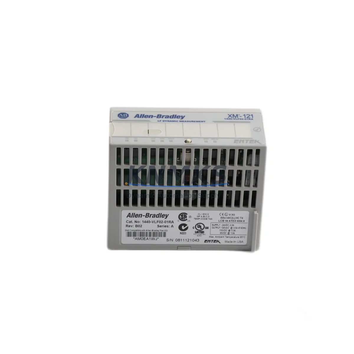
Allen-Bradley 1440-VLF02-01RA Maintenance-Proven Spare Part for Factory Uptime
The Allen-Bradley 1440-VLF02-01RA is a Velocity/Low-Frequency input module within the Rockwell Automation XM-21 Dynamic Measurement platform, engineered for continuous condition monitoring of rotating machinery in demanding industrial environments. As a critical node in vibration and dynamic signal acquisition chains, this module is routinely found in turbine protection panels, compressor monitoring racks, pump condition systems, and multi-axis machine health enclosures across petrochemical, power generation, pulp and paper, and heavy manufacturing facilities.
For maintenance engineers managing aging control infrastructure, the 1440-VLF02-01RA represents a high-priority spare. Its role in capturing low-frequency velocity signals means any degradation or failure directly impacts the plant’s ability to detect early-stage bearing wear, shaft imbalance, or misalignment — conditions that, left undetected, escalate into unplanned shutdowns. Stocking a verified replacement unit is not optional in high-availability environments; it is a core element of any credible predictive maintenance strategy.
KNMKS supplies the 1440-VLF02-01RA as an original spare part, individually tested prior to dispatch, with a support terms confirmed by quotation and full B2B procurement support. Units are available for immediate shipment to maintenance teams and procurement engineers worldwide.
Spare Maintenance Table
| Part Number | 1440-VLF02-01RA |
| Brand | Allen-Bradley / Rockwell Automation |
| Series | XM-21 Dynamic Measurement |
| Module Type | Velocity / Low-Frequency Input Module |
| Product Type | Dynamic Measurement Module |
| Input Channels | 2 dynamic input channels (velocity/low-frequency) |
| Signal Type | Velocity (low-frequency vibration), AC-coupled |
| Frequency Range | Low-frequency dynamic measurement (application-dependent) |
| Backplane Compatibility | XM Series backplane (1440-TB-A or equivalent) |
| Communication | DeviceNet via XM Series backplane |
| Power Supply | Supplied via XM backplane (24 VDC system bus) |
| Operating Temperature | 0°C to 60°C (32°F to 140°F) |
| Mounting | DIN rail / XM Series rack mount |
| Country of Origin | United States |
| Condition | Original spare, pre-shipment tested |
| Support terms | 12 months from date of shipment |
| Application | Rotating machinery condition monitoring, turbine/compressor/pump protection |
| Maintenance Recommendation | Inspect signal wiring and sensor connections during scheduled outages; verify channel calibration annually; replace immediately on alarm or channel fault indication |
Maintenance Planning for Continuous Operation
When the 1440-VLF02-01RA is flagged for replacement during a fault investigation or scheduled outage, experienced maintenance engineers treat the event as a trigger for a broader cabinet and loop inspection. The XM-21 system is rarely a standalone device — it operates as part of an integrated condition monitoring rack, and the health of adjacent components directly affects measurement accuracy and system reliability.
Begin by verifying the 24 VDC backplane power supply feeding the XM Series rack. A marginal or noisy power rail is a common root cause of intermittent module faults and should be confirmed before installing a replacement 1440-VLF02-01RA. The 1440-TB-A terminal base (or equivalent XM Series terminal base) should be inspected for corrosion, loose screw terminals, and proper seating — a degraded terminal base will cause recurring faults even with a new module installed.
Sensor wiring integrity is equally critical. The velocity transducers or seismic sensors connected to the module’s input channels should be checked for cable continuity, shield grounding, and connector condition. In high-vibration environments, cable fatigue at the sensor junction is a frequent failure point. If the plant uses signal isolators or signal conditioners upstream of the XM input, these should be tested for output accuracy and isolation resistance.
For facilities running the XM-21 system on a DeviceNet network, the network drop cable, termination resistors, and DeviceNet scanner module (such as the 1756-DNB in a ControlLogix rack) should be verified for proper configuration and communication health. A module swap without confirming network integrity can result in the replacement unit failing to come online correctly.
Procurement engineers building annual spare parts lists for XM-based condition monitoring systems should consider stocking the 1440-VFLS02-01RA (standard velocity/flux input variant) alongside the 1440-VLF02-01RA to cover adjacent channel types within the same rack. Additionally, XM Series backplane assemblies, terminal bases, and the associated 1440-REX00-04RD expansion modules are high-value additions to any XM system spare kit, as backplane failures are difficult to diagnose quickly under production pressure.
For control cabinets housing both XM modules and ControlLogix or CompactLogix PLCs, a cabinet-level inspection should include checking 1756-series I/O modules, power supply modules (such as the 1756-PA75), and any relay output modules wired to alarm or trip circuits driven by XM measurement data. Fuse integrity on the 24 VDC distribution rail and the condition of terminal blocks throughout the cabinet should also be documented during the same maintenance window.
Site Replacement Workflow
Step 1 — Pre-Replacement Verification: Confirm the fault is isolated to the 1440-VLF02-01RA by reviewing the XM system diagnostic LEDs and any fault codes reported via the DeviceNet scanner or RSLogix/Studio 5000 diagnostics. Document the existing module configuration (channel scaling, alarm setpoints, filter settings) before removal — this data is required for post-installation commissioning.
Step 2 — Safe Isolation: De-energize the XM rack following site LOTO procedures. The XM Series backplane distributes 24 VDC across all modules; confirm power is removed before extracting the module from the terminal base. Do not disconnect sensor wiring from the terminal base unless the wiring itself requires inspection.
Step 3 — Module Swap: Remove the faulty 1440-VLF02-01RA from the terminal base. Inspect the terminal base connector for damage. Insert the replacement unit, ensuring full engagement with the terminal base locking mechanism. The module is keyed to prevent incorrect installation within the XM rack.
Step 4 — Configuration Restore: Re-energize the rack and restore the module configuration using RSLogix 5000 / Studio 5000 or the XM Configuration Utility. Verify that all channel alarm setpoints, measurement ranges, and filter parameters match the pre-removal documentation. Confirm DeviceNet communication is re-established and the module status LED indicates normal operation.
Step 5 — Functional Verification: With the machinery running, verify that both input channels are returning valid dynamic measurements within expected ranges. Compare readings against historical baseline data to confirm the replacement module is performing correctly. Update the maintenance log with the replacement date, module serial number, and post-installation readings.
This workflow minimizes downtime, ensures system compatibility is maintained, and provides a documented audit trail for reliability engineering review.
Spare Parts Support FAQ
Q1: Is the 1440-VLF02-01RA supplied by KNMKS an original Allen-Bradley unit?
Yes. KNMKS supplies original Allen-Bradley / Rockwell Automation spare parts. Each 1440-VLF02-01RA unit is individually inspected and tested prior to shipment. A support terms confirmed by quotation is provided from the date of dispatch, covering manufacturing defects and functional failures under normal operating conditions.
Q2: How do I confirm compatibility with my existing XM-21 system before ordering?
The 1440-VLF02-01RA is designed for use within the Allen-Bradley XM Series Dynamic Measurement platform. Compatibility depends on your existing terminal base model and backplane configuration. Share your existing rack layout or terminal base part number with our technical team at admin@knmks.com and we will confirm compatibility before the order is placed.
Q3: What is the typical lead time and how is the unit prepared for shipment?
In-stock units are dispatched within 1–3 business days. Each module undergoes pre-shipment functional testing and is packaged in anti-static protective packaging suitable for international freight. Expedited shipping options are available for emergency maintenance situations. Contact us directly for urgent requirements.
Q4: Can KNMKS support long-term or repeat procurement for XM Series spare parts?
Yes. KNMKS maintains ongoing inventory of XM Series modules and related Allen-Bradley condition monitoring components to support planned maintenance programs, annual spare parts budgets, and emergency replacement needs. We offer B2B procurement agreements, volume pricing, and dedicated account support for facilities with recurring requirements.
—
© 2026 KNMKS. All rights reserved.
Original Source: https://knmks.com
Contact: admin@knmks.com | +86 18359268345
Product Identification
- Brand / Ecosystem
-
Allen-Bradley
Allen-Bradley - Model / Series
- 1440-VLF02-01RA
- Product Family
- PLCs & Controllers
- Availability Status
- Available on request after model and quantity confirmation
- Inquiry Type
- B2B RFQ, replacement inquiry and project spare-part request
- Pre-Quote Check
- Exact SKU, brand, series, quantity, nameplate photos and destination country are checked before quotation
System Path
Where this product fits in the KNMKS automation structure.
Specification & Inquiry Focus
- Control platform
- PLC, PAC and modular controllers
- Common needs
- CPU, rack, power and I/O expansion
- Project support
- Replacement, cabinet build and maintenance
Buyer Confirmation
Information KNMKS checks before replying.
- Exact model
- 1440-VLF02-01RA
- Brand / ecosystem
- Allen-Bradley
- Product family
- PLCs & Controllers
- Application note
- Replacement, maintenance, project build or spare-part list
- Useful photos
- Nameplate, installed unit, cabinet layout or connector side
- Delivery details
- Quantity, destination country and target schedule
Document Support
Files and notes can be confirmed during quotation.
- Product photos or nameplate confirmation when available
- Packing and delivery notes before quotation confirmation
- Support scope and delivery terms confirmed per inquiry
- Export document coordination for qualified B2B requests
Inquiry Support
- Model cross-checking before quotation
- CPU, power, rack and expansion module matching
- Support for replacement and project inquiry
What to Send Us
- Brand and exact model number: Allen-Bradley 1440-VLF02-01RA
- Quantity and required delivery time
- Application, replacement requirement or nameplate photo
- Destination country and shipping preference
RFQ Preparation
This is a product inquiry page built for RFQ communication.
Fast Model Check
Send this model to KNMKS for confirmation.
Include quantity, destination country and photos if this is a maintenance replacement. The inquiry will be saved with a reference number after submission.
Brand & Compatibility Note
KNMKS displays automation product information for well-known industrial brand ecosystems and compatible replacement references. Brand names are used for product identification and compatibility reference only; final availability and commercial terms are confirmed per quotation.
 Manufacturing
 Machine Tools
 Packaging
 Energy & Power
 HMI & Displays
 Servo Systems
 Variable Frequency Drives
 Sensors