
Overview
Allen-Bradley 1440-SPD02-01RB Migration-Ready Speed Module: Legacy System Retrofit and Compatible Upgrade
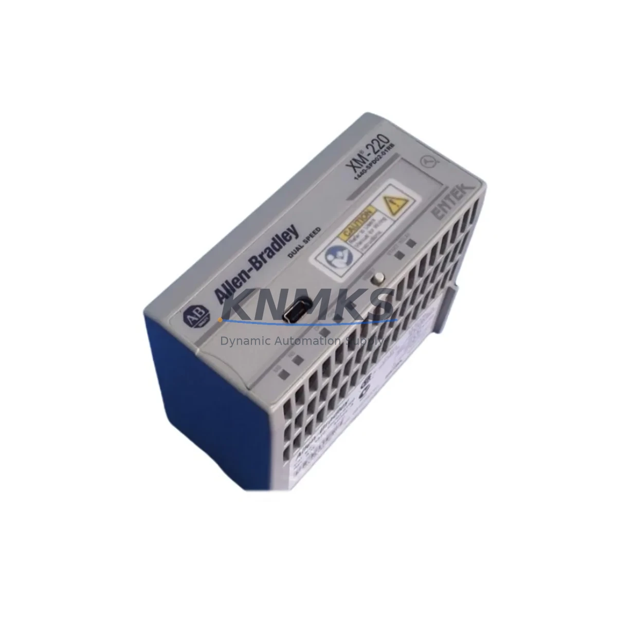
The Allen-Bradley 1440-SPD02-01RB is a dual-channel speed measurement module designed for the Rockwell Automation Dynamix 1440 condition monitoring platform. As legacy vibration and speed monitoring systems reach end-of-life or face discontinued spare parts availability, the 1440-SPD02-01RB provides a verified, migration-ready replacement path for maintenance engineers managing rotating equipment protection in refineries, power generation facilities, compressor stations, and heavy industrial plants.
This module accepts passive magnetic pickup (MPU) and active proximity probe inputs, delivering precise speed, overspeed, and underspeed detection across two independent channels. Its DIN rail-compatible form factor and standard terminal block wiring allow direct installation into existing Dynamix 1440 chassis without structural modification to the control cabinet. For sites currently operating legacy speed monitoring cards from discontinued platforms, the 1440-SPD02-01RB offers a functionally equivalent replacement that preserves existing wiring infrastructure and minimizes retrofit engineering hours.
Before committing to a replacement, engineers should verify the following critical parameters against the existing installation: input signal type (MPU vs. proximity probe), channel count requirements, power supply rail compatibility within the 1440 chassis, module slot addressing in the Dynamix 1440 configuration software, and the firmware revision of the host chassis backplane. In multi-module racks, the 1440-MOD-D4IOE2 I/O expansion module and the 1440-TB-A terminal base assembly are commonly installed alongside the speed module and should be confirmed as compatible with the current rack revision before ordering.
Sites running integrated condition monitoring programs that combine speed data with vibration analysis will typically pair the 1440-SPD02-01RB with the 1440-VA04-01RA four-channel vibration module and the 1440-DYN02-01RJ dynamic measurement module. These modules share the same Dynamix 1440 backplane communication architecture, ensuring synchronized data acquisition across speed and vibration channels without requiring additional communication wiring or protocol converters.
All units are tested prior to shipment, supplied with a support terms confirmed by quotation, and available from in-stock inventory to support urgent maintenance and unplanned outage scenarios.
Migration Compatibility Table
| Parameter | Detail |
|---|---|
| SKU / Part Number | 1440-SPD02-01RB |
| Platform | Rockwell Automation Dynamix 1440 |
| Module Function | Dual-Channel Speed Measurement (MPU & Proximity Probe) |
| Input Signal Types | Passive MPU, Active Proximity Probe (24 VDC) |
| Channel Count | 2 Independent Speed Channels |
| Backplane Interface | Dynamix 1440 Series Backplane (standard slot) |
| Terminal Base | Compatible with 1440-TB-A Terminal Base Assembly |
| Power Supply | Supplied via Dynamix 1440 chassis backplane rail |
| Installation | DIN Rail, direct slot insertion — no cabinet modification required |
| Communication | Backplane-native; integrates with Dynamix 1440 host controller |
| Replacement Compatibility | Drop-in for legacy Dynamix 1440 speed monitoring cards |
| Firmware Requirement | Verify host chassis firmware revision before installation |
| Commissioning | Configure via Dynamix 1440 configuration software; verify channel address assignment |
| Support terms | 12 Months from date of shipment |
| Stock Status | availability confirmed by RFQ — available for immediate dispatch |
| Pre-Shipment Test | Function-tested prior to dispatch |
| Country of Origin | China (CN) |
Retrofit Planning for Existing Automation Systems
Successful integration of the 1440-SPD02-01RB into an existing condition monitoring system requires a structured pre-retrofit assessment. Begin by auditing the current Dynamix 1440 rack configuration: document all occupied module slots, confirm the chassis revision, and identify the terminal base assemblies (1440-TB-A) associated with the speed monitoring positions. If the existing installation uses a 1440-MOD-D4IOE2 I/O expansion module for relay output or discrete signal routing, verify that the expansion module firmware is compatible with the replacement speed module before proceeding.
Power budget confirmation is a critical step that is frequently overlooked in speed module replacements. The Dynamix 1440 chassis power supply — typically a 1440-PS-DC24 or equivalent — must have sufficient headroom to support the replacement module alongside all co-installed vibration, dynamic measurement, and I/O modules. Calculate the total current draw across all installed modules and compare against the rated output of the chassis power supply before finalizing the bill of materials.
Wiring adaptation is generally straightforward for MPU-type sensors, as the 1440-SPD02-01RB uses the same terminal block pinout as predecessor speed modules in the Dynamix 1440 family. However, sites transitioning from active proximity probe inputs should confirm the probe supply voltage (typically 24 VDC) and verify that the existing field cable shielding and grounding scheme meets the module’s input specifications. Where signal integrity is a concern — particularly in high-EMI environments near variable frequency drives or large motor starters — the addition of a signal isolator between the field sensor and the module input terminal may be advisable.
For sites that also operate a 1440-VA04-01RA vibration module in the same rack, the speed channel data from the 1440-SPD02-01RB is used as the reference signal for synchronous vibration analysis (1X, 2X vector tracking). Confirm that the speed channel assignment in the Dynamix 1440 configuration software correctly references the replacement module’s slot address to avoid disrupting existing vibration alarm setpoints and trend data.
HMI screen updates should be planned as part of the retrofit scope. If the plant DCS or SCADA system displays speed data sourced from the Dynamix 1440 platform, verify that the tag mapping between the Dynamix 1440 host controller and the upstream control system remains intact after the module replacement. In most cases, the tag structure is preserved when the replacement module occupies the same slot address as the original, but this should be confirmed during the pre-commissioning walkthrough.
Downtime Control During System Migration
Minimizing unplanned downtime during a speed module replacement requires careful sequencing of the retrofit activities. Where process conditions permit, schedule the module swap during a planned maintenance window rather than responding reactively to a module failure. Pre-stage the 1440-SPD02-01RB alongside all required accessories — terminal base, mounting hardware, and configuration laptop with the appropriate Dynamix 1440 software version — before initiating the shutdown sequence.
Prior to removing the existing speed module, export the current Dynamix 1440 configuration file and store it in a secure backup location. This configuration file contains all channel setpoints, alarm thresholds, speed reference assignments, and communication parameters. In the event of an unexpected issue during commissioning of the replacement module, the backed-up configuration allows rapid restoration of the previous operating state without requiring manual re-entry of all parameters.
During the physical swap, follow the Dynamix 1440 module removal procedure: de-energize the chassis if required by site safety procedures, release the module locking tab, extract the module from the terminal base, and insert the 1440-SPD02-01RB into the same slot. The terminal base wiring remains undisturbed throughout this process, which is a key advantage of the Dynamix 1440 modular architecture and a primary reason why this platform is preferred for retrofit applications in operating plants.
After insertion, restore power to the chassis and allow the module to complete its self-diagnostic sequence. Load the backed-up configuration file and verify that all channel parameters have been correctly applied. Perform a live speed signal check by observing the module’s channel indicators and confirming that the speed reading displayed in the Dynamix 1440 software matches the expected value from the field sensor. Once both channels are confirmed operational, update the maintenance record and notify the control room that the system has been returned to service. Total elapsed time for a well-prepared module swap is typically under two hours, including configuration verification and documentation.
Retrofit Support FAQ
Q1: Is the 1440-SPD02-01RB a direct drop-in replacement for the original Dynamix 1440 speed module in my existing rack?
In most cases, yes. The 1440-SPD02-01RB is designed for the Dynamix 1440 platform and uses the same backplane interface and terminal base (1440-TB-A) as the original speed monitoring modules in this series. Confirm the chassis revision and firmware version of your host controller before installation to ensure full compatibility.
Q2: What wiring changes are required when replacing a legacy speed module with the 1440-SPD02-01RB?
For MPU-type sensor inputs, no wiring changes are typically required — the existing field cables connect to the same terminal positions on the 1440-TB-A terminal base. For active proximity probe inputs, verify the probe supply voltage and cable shielding scheme against the module’s input specifications. In high-EMI environments, a signal isolator may be recommended between the field sensor and the module input.
Q3: How do I verify that the replacement module is functioning correctly after installation?
After inserting the 1440-SPD02-01RB and loading the configuration file, observe the channel status indicators on the module face and confirm that the speed reading in the Dynamix 1440 configuration software matches the expected value from the field sensor. Check that all alarm setpoints are active and that the speed data is being correctly transmitted to the upstream DCS or SCADA system via the Dynamix 1440 host controller.
Q4: What support terms and stock availability does this module carry?
All 1440-SPD02-01RB units supplied by KNMKS carry a support terms confirmed by quotation from the date of shipment and are function-tested prior to dispatch. Units are available from in-stock inventory for immediate shipment, supporting both planned maintenance programs and urgent unplanned replacement requirements.
© 2026 KNMKS. All rights reserved.
Original Source: https://knmks.com
Contact: admin@knmks.com | +86 18359268345
Product Identification
- Brand / Ecosystem
-
Allen-Bradley
Allen-Bradley - Model / Series
- 1440-SPD02-01RB
- Product Family
- PLCs & Controllers
- Availability Status
- Available on request after model and quantity confirmation
- Inquiry Type
- B2B RFQ, replacement inquiry and project spare-part request
- Pre-Quote Check
- Exact SKU, brand, series, quantity, nameplate photos and destination country are checked before quotation
System Path
Where this product fits in the KNMKS automation structure.
Specification & Inquiry Focus
- Control platform
- PLC, PAC and modular controllers
- Common needs
- CPU, rack, power and I/O expansion
- Project support
- Replacement, cabinet build and maintenance
Buyer Confirmation
Information KNMKS checks before replying.
- Exact model
- 1440-SPD02-01RB
- Brand / ecosystem
- Allen-Bradley
- Product family
- PLCs & Controllers
- Application note
- Replacement, maintenance, project build or spare-part list
- Useful photos
- Nameplate, installed unit, cabinet layout or connector side
- Delivery details
- Quantity, destination country and target schedule
Document Support
Files and notes can be confirmed during quotation.
- Product photos or nameplate confirmation when available
- Packing and delivery notes before quotation confirmation
- Support scope and delivery terms confirmed per inquiry
- Export document coordination for qualified B2B requests
Inquiry Support
- Model cross-checking before quotation
- CPU, power, rack and expansion module matching
- Support for replacement and project inquiry
What to Send Us
- Brand and exact model number: Allen-Bradley 1440-SPD02-01RB
- Quantity and required delivery time
- Application, replacement requirement or nameplate photo
- Destination country and shipping preference
RFQ Preparation
This is a product inquiry page built for RFQ communication.
Fast Model Check
Send this model to KNMKS for confirmation.
Include quantity, destination country and photos if this is a maintenance replacement. The inquiry will be saved with a reference number after submission.
Brand & Compatibility Note
KNMKS displays automation product information for well-known industrial brand ecosystems and compatible replacement references. Brand names are used for product identification and compatibility reference only; final availability and commercial terms are confirmed per quotation.
 Manufacturing
 Machine Tools
 Packaging
 Energy & Power
 HMI & Displays
 Servo Systems
 Variable Frequency Drives
 Sensors