
Overview
ABB PEP21023 Migration-Ready Dual Chassis Expansion for Legacy PLC Systems
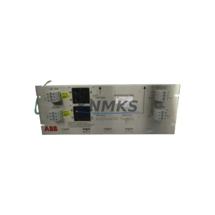
The ABB PEP21023 is a dual chassis expansion module engineered for the AC500 PLC platform, purpose-built to support legacy control system modernization without requiring full panel redesign. As industrial facilities face increasing pressure to replace discontinued backplane and rack components, the PEP21023 provides a direct migration path that preserves existing wiring infrastructure, I/O addressing, and program logic. Whether you are upgrading from an older AC500 V1 configuration or consolidating a multi-rack control cabinet, this module delivers the physical and electrical compatibility required for a controlled, low-risk retrofit.
The PEP21023 connects two AC500 CPU racks via a dedicated expansion bus, enabling distributed I/O placement across separate mounting rails within the same control cabinet or across adjacent enclosures. This architecture is particularly valuable in retrofit scenarios where the original control cabinet has limited DIN rail space and the engineering team must distribute signal modules — such as the ABB DC532 digital input module or the ABB AX522 analog I/O module — across multiple chassis without introducing additional communication latency or protocol conversion overhead. The expansion link operates transparently to the CPU, meaning existing program logic, function block references, and HMI variable mappings remain valid after the chassis extension is installed.
During retrofit planning, engineers must verify several critical parameters before commissioning the PEP21023. Power budget across the expanded chassis is the first checkpoint: the total current draw of all installed I/O modules on both the primary and secondary racks must remain within the rated capacity of the PM573-ETH or PM592-ETH CPU power supply. If the existing power supply is already near its rated output, a supplementary ABB CP-E 24/5.0 DIN-rail power supply unit should be added to the secondary chassis before module population. Terminal wiring on the secondary rack must be re-verified against the original I/O list, as physical slot positions may shift when the expansion chassis is introduced, potentially affecting module address assignments in the AC500 configuration tool (Automation Builder).
Backplane interface compatibility is another key consideration. The PEP21023 uses the standard AC500 internal bus connector, which is mechanically and electrically compatible with the current generation of AC500 V2 and V3 CPU modules. However, if the existing installation uses legacy V1-era terminal units such as the TU515 or TU516, the engineering team should audit each terminal unit’s firmware revision and confirm compatibility with the expansion bus timing parameters. In most cases, a firmware update to the CPU — applied via the SD card slot or the Automation Builder programming interface — resolves any timing mismatches without requiring hardware replacement.
Communication link integrity must also be validated during the retrofit. If the control system includes a CM572-DP PROFIBUS master module or a CM589-PNIO PROFINET interface module installed in the primary chassis, the expansion to a secondary chassis via PEP21023 does not affect the communication module’s network address or its slave device table. However, the physical cable routing between the two chassis should be reviewed to ensure the expansion bus cable is not routed alongside high-voltage conductors, which can introduce noise on the internal bus and cause intermittent diagnostic faults. Shielded cable routing and proper grounding of the secondary chassis frame are standard commissioning requirements for this configuration.
For facilities managing a phased migration — where some legacy I/O remains active on the old rack while new modules are brought online on the expansion chassis — the PEP21023 supports a staged cutover approach. The CPU continues to scan both chassis simultaneously, allowing the maintenance team to verify new I/O wiring and signal integrity on the secondary rack before transferring control logic references from the old module addresses to the new ones. This approach minimizes unplanned downtime and allows the HMI screens — typically built on ABB CP600 or CP635 operator panels — to be updated incrementally rather than requiring a full screen rebuild during a single maintenance window.
Outgoing testing at our facility includes a full power-on verification of the expansion bus link, confirmation of module recognition across both chassis, and a functional check of the internal bus communication under simulated load. Each PEP21023 unit ships with a support terms confirmed by quotation covering manufacturing defects and bus interface failures. Units are available from regional stock and can be dispatched within standard lead times to support planned maintenance shutdowns or emergency replacement requirements.
Migration Compatibility Table
| Parameter | Details |
|---|---|
| Compatible Platform | ABB AC500 V2 / V3 (PM554, PM564, PM573, PM583, PM592, PM595) |
| Expansion Bus Interface | AC500 internal bus connector (standard backplane) |
| Max Modules per Chassis | Up to 10 I/O or communication modules per rack |
| Installation Requirement | DIN rail mount; verify rail spacing and cabinet depth before installation |
| Power Supply Compatibility | Requires dedicated power feed to secondary chassis; verify CPU PSU budget |
| Communication Compatibility | Transparent to PROFIBUS (CM572-DP), PROFINET (CM589-PNIO), Modbus TCP |
| Firmware Requirement | AC500 CPU firmware ≥ V2.x recommended; update via Automation Builder or SD card |
| Replacement Recommendation | Direct replacement for legacy AC500 V1 dual-rack expansion configurations |
| Commissioning Focus | Module address verification, power budget check, bus cable shielding, HMI variable re-mapping |
| Support terms | 12 months from shipment date, covering manufacturing defects and bus interface failures |
Retrofit Planning for Existing Automation Systems
A successful PEP21023 retrofit begins with a complete audit of the existing AC500 rack configuration. Document every installed module — including the CPU module (e.g., PM573-ETH or PM592-ETH), all I/O modules such as the DC532 digital input or DA501 digital output, any analog signal modules like the AX522, and communication interfaces including the CM572-DP or CM589-PNIO — along with their current slot positions and configured addresses in Automation Builder. This baseline inventory becomes the reference for address mapping on the expanded chassis.
Next, assess the physical installation space. The secondary chassis introduced by the PEP21023 requires its own DIN rail segment, typically mounted below or adjacent to the primary rack. Measure available cabinet depth and rail length before ordering, as the AC500 terminal units (TU515, TU516, TU531) have specific depth profiles that must clear cable duct and door-mounted components. If the control cabinet is a legacy enclosure with limited internal volume, consider whether a supplementary enclosure section or a new panel is required as part of the modernization scope.
Power distribution planning is equally critical. The secondary chassis must receive a dedicated 24 VDC supply, either from the existing panel power supply if headroom permits, or from a dedicated ABB CP-E 24/5.0 or equivalent DIN-rail power supply unit. Verify the total current draw of all modules planned for the secondary rack against the supply’s rated output, including derating for ambient temperature in the installation environment.
Finally, prepare the programming environment. Open the existing Automation Builder project, add the PEP21023 expansion configuration to the hardware tree, and assign the secondary chassis modules to their new slot addresses. Export the updated I/O variable list and cross-reference it against the HMI project — particularly any CP600 or CP635 panel screens that reference I/O tags by address — to identify variables that require remapping before the cutover window begins.
Downtime Control During System Migration
Minimizing unplanned downtime during a PEP21023 installation requires a structured pre-commissioning sequence. Before the maintenance window opens, complete all hardware preparation offline: mount the secondary chassis on the DIN rail, install all planned I/O modules into their designated slots, wire all field terminals to the terminal units, and verify continuity on all signal circuits. When the maintenance window begins, the only on-line steps required are connecting the expansion bus cable between the primary and secondary chassis, applying power to the secondary chassis supply, and performing a CPU restart to recognize the new hardware configuration.
Protect the original program logic by exporting a full project backup from Automation Builder — including the hardware configuration, POU source code, and variable tables — before making any changes to the project file. Store this backup on a separate USB drive or network location accessible from the commissioning laptop. If the retrofit introduces any address changes, maintain the original address assignments in a parallel variable table until the new addresses have been verified in the field, then perform a controlled switchover within the program rather than modifying the field wiring.
HMI continuity is maintained by updating the CP600 or CP635 panel project in parallel with the PLC project, using the same variable remapping table. Where possible, test the updated HMI project on a simulator or a spare panel before deploying it to the production operator station. This approach ensures that process operators see consistent screen behavior throughout the cutover and that alarm setpoints, trend histories, and recipe parameters are preserved without manual re-entry.
After the expansion chassis is online and all I/O modules are recognized by the CPU, perform a structured loop check: verify each digital input and output by forcing signals from the Automation Builder online monitor, and verify each analog channel against a calibrated signal source. Document the results in the commissioning record before releasing the system to production. This structured approach typically allows a PEP21023 expansion to be completed within a single planned maintenance window of four to eight hours, depending on the number of I/O points being migrated.
Retrofit Support FAQ
Q: Is the PEP21023 a direct drop-in replacement for the legacy AC500 V1 dual chassis expansion interface?
A: Yes. The PEP21023 uses the same AC500 internal bus connector and is mechanically compatible with the standard AC500 DIN-rail mounting system. In most V1-to-V2 migration scenarios, no wiring changes are required on the primary chassis side. Verify CPU firmware version before installation.
Q: What commissioning steps are required after installing the PEP21023?
A: After physically connecting the expansion bus cable and powering the secondary chassis, restart the AC500 CPU and open the Automation Builder online monitor to confirm that all modules on the secondary rack are recognized and reporting no diagnostic faults. Perform a full I/O loop check on all secondary chassis modules before returning the system to automatic operation.
Q: Can the PEP21023 be used with PROFIBUS or PROFINET communication modules installed in the primary chassis?
A: Yes. The expansion bus operates independently of the communication module interfaces. CM572-DP PROFIBUS and CM589-PNIO PROFINET modules installed in the primary chassis continue to operate normally after the secondary chassis is added. No changes to the PROFIBUS or PROFINET network configuration are required.
Q: What does the support terms confirmed by quotation cover, and is pre-shipment testing performed?
A: Each PEP21023 unit undergoes a power-on functional test and expansion bus communication verification before shipment. The support terms confirmed by quotation cover manufacturing defects and bus interface failures under normal operating conditions. Units are dispatched from regional stock to support both planned retrofit projects and emergency replacement requirements.
© 2026 KNMKS. All rights reserved.
Original Source: https://knmks.com
Contact: admin@knmks.com | +86 18359268345
Product Identification
- Brand / Ecosystem
-
ABB
ABB - Model / Series
-
PEP21023
AC500 Series - Product Family
- PLCs & Controllers
- Availability Status
- Available on request after model and quantity confirmation
- Inquiry Type
- B2B RFQ, replacement inquiry and project spare-part request
- Pre-Quote Check
- Exact SKU, brand, series, quantity, nameplate photos and destination country are checked before quotation
System Path
Where this product fits in the KNMKS automation structure.
Specification & Inquiry Focus
- Control platform
- PLC, PAC and modular controllers
- Common needs
- CPU, rack, power and I/O expansion
- Project support
- Replacement, cabinet build and maintenance
Buyer Confirmation
Information KNMKS checks before replying.
- Exact model
- PEP21023
- Brand / ecosystem
- ABB
- Product family
- PLCs & Controllers
- Application note
- Replacement, maintenance, project build or spare-part list
- Useful photos
- Nameplate, installed unit, cabinet layout or connector side
- Delivery details
- Quantity, destination country and target schedule
Document Support
Files and notes can be confirmed during quotation.
- Product photos or nameplate confirmation when available
- Packing and delivery notes before quotation confirmation
- Support scope and delivery terms confirmed per inquiry
- Export document coordination for qualified B2B requests
Inquiry Support
- Model cross-checking before quotation
- CPU, power, rack and expansion module matching
- Support for replacement and project inquiry
What to Send Us
- Brand and exact model number: ABB PEP21023
- Quantity and required delivery time
- Application, replacement requirement or nameplate photo
- Destination country and shipping preference
RFQ Preparation
This is a product inquiry page built for RFQ communication.
Fast Model Check
Send this model to KNMKS for confirmation.
Include quantity, destination country and photos if this is a maintenance replacement. The inquiry will be saved with a reference number after submission.
Brand & Compatibility Note
KNMKS displays automation product information for well-known industrial brand ecosystems and compatible replacement references. Brand names are used for product identification and compatibility reference only; final availability and commercial terms are confirmed per quotation.
 Manufacturing
 Machine Tools
 Packaging
 Energy & Power
 HMI & Displays
 Servo Systems
 Variable Frequency Drives
 Sensors