
Overview
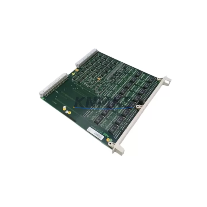
ABB MAI32LAD Migration-Ready Analog Input for AC500 S500: Legacy System Migration and Compatible Upgrade
The ABB MAI32LAD is a 32-channel analog input module engineered for the AC500 S500 PLC platform, widely deployed across process automation, building management, and discrete manufacturing environments. As legacy AC500 installations approach end-of-service milestones, the MAI32LAD has become a critical retrofit component for engineers tasked with extending system life, replacing discontinued I/O modules, and migrating aging control architectures to current-generation hardware without full panel redesign.
When planning a retrofit around the MAI32LAD, the first step is confirming power budget on the existing S500 backplane. The module draws from the local bus supply, and engineers must verify that the PM581, PM582, or PM591 CPU module’s power rail can accommodate the additional analog load alongside existing digital I/O cards. Terminal wiring follows the standard S500 screw-terminal convention, so field cables from legacy MAI32 or MAI32L installations can typically be re-terminated without re-labeling, significantly reducing downtime during changeover.
Backplane slot addressing is handled automatically by the AC500 system bus, but the module’s logical address must be confirmed in the Control Builder Plus project before going live. If the original program was developed on an older Control Builder M environment, a project migration step is required to re-map I/O addresses to the new module instance. This is particularly important when the MAI32LAD is replacing a discontinued MAI32 variant, as channel scaling parameters and filter time constants may differ between firmware generations.
Communication compatibility is a key consideration in multi-network installations. The AC500 S500 platform supports PROFIBUS DP via the CI502-PNIO or CI504-PNIO communication interface modules, and Modbus TCP through the CM589-PNIO Ethernet coupler. When the MAI32LAD is integrated into a system that also includes a CI501-PNIO PROFIBUS master or a CI541-DP slave coupler, engineers should verify that the GSD file version in the PROFIBUS configurator matches the firmware revision on the communication module. Mismatched GSD versions are a common source of diagnostic alarms during first power-up after a retrofit.
For installations where the MAI32LAD is being added to expand an existing S500 rack, physical space confirmation is essential. The S500 backplane accepts up to 10 I/O modules per segment, and if the existing rack is fully populated, a TB521-ETH or TB511 terminal base expansion may be required. Engineers should also confirm that the DIN rail depth and cabinet door clearance accommodate the module’s front-face wiring harness before ordering.
HMI screen updates are frequently overlooked during analog input module replacements. If the plant SCADA or Panel Builder 600 HMI references specific channel tags from the legacy module, those tag bindings must be updated to reflect the new I/O address map. Failure to update HMI tag references is one of the most common causes of post-retrofit alarm floods and operator confusion during the first production shift after changeover.
Firmware version alignment between the MAI32LAD and the host CPU is verified during the Control Builder Plus hardware configuration scan. ABB recommends running a firmware update on the CPU — typically a PM591 or PM592 — before installing the new module to ensure full feature compatibility, particularly for advanced analog diagnostics such as wire-break detection and over-range flagging.
All MAI32LAD units supplied by KNMKS are pre-shipment tested under simulated AC500 bus conditions, verifying channel-by-channel analog response, bus communication handshake, and diagnostic register integrity. Each unit ships with a support terms confirmed by quotation covering manufacturing defects and functional failure under normal operating conditions. Stock is maintained across multiple regional warehouses to support rapid dispatch for emergency breakdown replacements and planned maintenance windows alike.
Migration Compatibility Table
| Parameter | MAI32LAD (Current) | Legacy MAI32 / MAI32L | Retrofit Notes |
|---|---|---|---|
| Analog Channels | 32 (single-ended) | 32 (single-ended) | Direct channel-count match; re-use existing field wiring |
| Input Range | 0–10 V / 0–20 mA / 4–20 mA | 0–10 V / 0–20 mA | Confirm DIP switch / software range setting per channel |
| Backplane Interface | S500 local bus | S500 local bus | Slot-compatible; no backplane adapter required |
| Communication | PROFIBUS DP, Modbus RTU/TCP | PROFIBUS DP | Verify GSD file version in PROFIBUS configurator |
| Terminal Wiring | Screw terminal, 0.5–2.5 mm² | Screw terminal, 0.5–2.5 mm² | Field cables re-terminable without re-labeling |
| Power Consumption | ~1.2 W (bus supply) | ~1.0 W (bus supply) | Verify CPU power budget before installation |
| Firmware Compatibility | Control Builder Plus v2.x+ | Control Builder M / Plus | Project migration required for CBM-origin programs |
| Installation Space | Standard S500 slot width | Standard S500 slot width | Confirm rack slot availability; max 10 modules/segment |
| Commissioning Tool | Control Builder Plus | Control Builder M / Plus | Run hardware scan after installation to confirm address |
| Support terms | support terms confirmed by quotation — All units pre-shipment tested | ||
Retrofit Planning for Existing Automation Systems
A successful MAI32LAD retrofit begins with a structured audit of the existing S500 rack configuration. Engineers should document the current slot assignments of all installed modules — including the PM591 or PM592 CPU, any CI502-PNIO or CI504-PNIO communication interface cards, and existing digital I/O modules such as the DAI531 or DAI543 — before removing the legacy analog input card. This snapshot becomes the reference for restoring the hardware configuration in Control Builder Plus after the new module is seated.
Power supply sizing is the next critical checkpoint. The S500 system draws from a dedicated PS501 or PS502 power supply module, and adding or replacing analog I/O cards changes the total bus current draw. Engineers should calculate the aggregate load across all installed modules and confirm that the power supply’s rated output — typically 2 A or 4 A at 24 VDC — provides at least 20% headroom above the calculated load to prevent nuisance trips during cold-start inrush.
Signal isolation requirements should be evaluated for each analog input channel. In installations where field sensors share a common ground with variable-frequency drives or other noise-generating equipment, adding a signal isolator between the field device and the MAI32LAD input terminal can prevent ground loop interference that would otherwise corrupt analog readings. This is especially relevant in retrofit scenarios where the original system design predates modern EMC best practices.
Programming cable access is required during commissioning. A TK501 USB programming cable or equivalent Ethernet connection to the CM589-PNIO coupler provides the Control Builder Plus link needed to perform the hardware scan, download the updated program, and verify analog channel diagnostics in online mode. Engineers should confirm cable availability and laptop compatibility before scheduling the maintenance window.
For systems where the MAI32LAD is being installed alongside a new TB521-ETH terminal base or expanded S500 rack segment, the physical installation sequence matters: seat the terminal base first, confirm DIN rail locking, then insert the module and apply power before initiating the Control Builder Plus scan. This sequence prevents bus initialization errors that can occur when modules are inserted into a powered rack without a prior hardware configuration update.
Downtime Control During System Migration
Minimizing production downtime during an analog input module replacement requires preparation that begins well before the maintenance window opens. The most effective approach is to export the current Control Builder Plus project, create a hardware configuration branch with the MAI32LAD substituted for the legacy module, and perform a full offline simulation to verify that all analog tag references, scaling blocks, and alarm limits resolve correctly in the new configuration. This offline validation step typically takes two to four hours but can prevent a multi-shift recovery effort if an addressing conflict is discovered after the system is already offline.
During the physical swap, the recommended sequence is: save the current CPU program to a backup file on the engineering laptop, set the CPU to STOP mode via Control Builder Plus, remove the legacy module from its slot, insert the MAI32LAD, and perform a hardware scan before switching the CPU back to RUN mode. This sequence preserves the original program logic in memory and allows the engineer to restore the previous configuration quickly if the new module fails to initialize correctly.
Field control continuity can be maintained during short-duration swaps by placing downstream control loops in manual mode at the DCS or SCADA level before the CPU is stopped. This prevents runaway actuator behavior during the period when analog feedback signals are unavailable. Once the MAI32LAD is online and analog readings are confirmed stable in Control Builder Plus, the loops can be returned to automatic mode in a controlled sequence, starting with the least critical process variables and working toward the most sensitive control loops.
Post-retrofit verification should include a channel-by-channel analog input check using a calibrated signal source to confirm that each of the 32 channels reads within the expected engineering unit range. Any channel that shows an offset or scaling error should be investigated before the system is returned to full production, as analog input errors in process control applications can propagate into incorrect actuator commands and product quality deviations.
Retrofit Support FAQ
Q: Is the MAI32LAD a direct drop-in replacement for the legacy MAI32 and MAI32L modules?
A: The MAI32LAD is slot-compatible with the S500 backplane and uses the same screw-terminal wiring convention as the MAI32 and MAI32L. Field cables can typically be re-terminated without modification. However, a Control Builder Plus hardware configuration update and program download are required to register the new module’s I/O address, and channel input range settings should be verified against the original configuration before returning the system to service.
Q: What commissioning steps are required after installing the MAI32LAD?
A: After physical installation, connect a TK501 USB programming cable or Ethernet link to the CM589-PNIO coupler and open the Control Builder Plus project. Run a hardware scan to detect the new module, confirm the slot address assignment, download the updated hardware configuration to the CPU, and verify analog channel readings in online mode using a calibrated signal source. Check diagnostic registers for any wire-break or over-range flags before switching the CPU to RUN mode.
Q: Can the MAI32LAD operate in a PROFIBUS DP network alongside legacy S500 modules?
A: Yes. The MAI32LAD communicates via the S500 local bus and does not require a dedicated PROFIBUS address. PROFIBUS DP connectivity is provided by the CI502-PNIO or CI504-PNIO communication interface module installed in the same rack. Ensure the GSD file version in the PROFIBUS master configurator matches the firmware revision on the communication interface module to avoid diagnostic alarms during network initialization.
Q: What support terms and pre-shipment testing does KNMKS provide for the MAI32LAD?
A: All MAI32LAD units supplied by KNMKS are pre-shipment tested under simulated AC500 bus conditions, covering channel-by-channel analog response, bus communication handshake, and diagnostic register integrity. Each unit is covered by a support terms confirmed by quotation against manufacturing defects and functional failure under normal operating conditions. Stock is available for immediate dispatch to support both emergency breakdown replacements and planned maintenance schedules.
© 2026 KNMKS. All rights reserved. Original Source: https://knmks.com | Contact: admin@knmks.com | +86 18359268345
Product Identification
- Brand / Ecosystem
-
ABB
ABB - Model / Series
-
MAI32LAD
AC500 Series - Product Family
- PLCs & Controllers
- Availability Status
- Available on request after model and quantity confirmation
- Inquiry Type
- B2B RFQ, replacement inquiry and project spare-part request
- Pre-Quote Check
- Exact SKU, brand, series, quantity, nameplate photos and destination country are checked before quotation
System Path
Where this product fits in the KNMKS automation structure.
Specification & Inquiry Focus
- Control platform
- PLC, PAC and modular controllers
- Common needs
- CPU, rack, power and I/O expansion
- Project support
- Replacement, cabinet build and maintenance
Buyer Confirmation
Information KNMKS checks before replying.
- Exact model
- MAI32LAD
- Brand / ecosystem
- ABB
- Product family
- PLCs & Controllers
- Application note
- Replacement, maintenance, project build or spare-part list
- Useful photos
- Nameplate, installed unit, cabinet layout or connector side
- Delivery details
- Quantity, destination country and target schedule
Document Support
Files and notes can be confirmed during quotation.
- Product photos or nameplate confirmation when available
- Packing and delivery notes before quotation confirmation
- Support scope and delivery terms confirmed per inquiry
- Export document coordination for qualified B2B requests
Inquiry Support
- Model cross-checking before quotation
- CPU, power, rack and expansion module matching
- Support for replacement and project inquiry
What to Send Us
- Brand and exact model number: ABB MAI32LAD
- Quantity and required delivery time
- Application, replacement requirement or nameplate photo
- Destination country and shipping preference
RFQ Preparation
This is a product inquiry page built for RFQ communication.
Fast Model Check
Send this model to KNMKS for confirmation.
Include quantity, destination country and photos if this is a maintenance replacement. The inquiry will be saved with a reference number after submission.
Brand & Compatibility Note
KNMKS displays automation product information for well-known industrial brand ecosystems and compatible replacement references. Brand names are used for product identification and compatibility reference only; final availability and commercial terms are confirmed per quotation.
 Manufacturing
 Machine Tools
 Packaging
 Energy & Power
 HMI & Displays
 Servo Systems
 Variable Frequency Drives
 Sensors