
Overview
ABB GJR2393200R1210 88TK05C-E Migration-Ready Bus Coupler for Legacy Control Systems
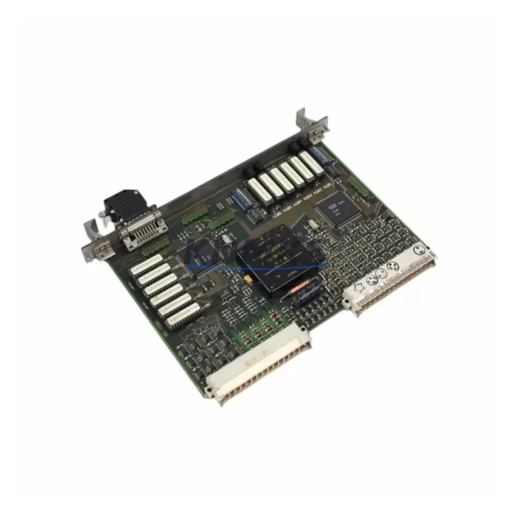
The ABB GJR2393200R1210 (88TK05C-E) is a station bus coupler module designed for the ABB AC500 PLC platform, serving as a critical interface between the central processing unit and distributed I/O stations across the station bus. As legacy AC500 installations age and original couplers reach end-of-life, this module provides a verified migration path for facilities managing discontinued spare parts, aging control cabinets, and long-term production continuity requirements.
Industrial maintenance teams replacing obsolete bus couplers must confirm several parameters before commissioning: station bus termination settings, module address assignment via DIP switch or software configuration, backplane slot compatibility within the AC500 rack, and firmware version alignment with the active CPU firmware. The GJR2393200R1210 supports both Modbus RTU and PROFIBUS DP communication stacks depending on configuration, making it suitable for mixed-protocol environments where legacy field devices and newer distributed I/O coexist on the same control network.
When integrating this coupler into an existing AC500 rack alongside modules such as the SM560 CPU or DC532 digital I/O modules, engineers should verify that the total station bus current draw does not exceed the power supply module’s rated output — typically the PM573 or PM591 power supply units used in AC500 cabinets. Exceeding bus current limits causes intermittent communication faults that are difficult to diagnose under load. Pre-installation power budget review is strongly recommended.
Terminal wiring on the station bus connector must match the original installation’s cable shielding and grounding scheme. In retrofit scenarios where the original coupler used a different terminal pitch or connector type, an adapter terminal block may be required. Documenting the existing wiring before removal — including signal polarity, shield drain connections, and cable routing — significantly reduces commissioning time and the risk of introducing ground loops into the control network.
For facilities migrating from older S500 or Advant OCS control architectures to AC500, the GJR2393200R1210 bus coupler is frequently deployed alongside CI590 communication interface modules and TB511 terminal base units to reconstruct distributed I/O stations with minimal changes to the existing field wiring. This approach preserves the original I/O channel assignments and allows the PLC program logic — including function block libraries and HMI screen tag mappings — to remain largely unchanged, reducing validation effort and downtime exposure during cutover.
HMI screen updates are often overlooked during bus coupler replacements. If the original coupler used a node address that differs from the replacement unit’s default, all HMI data links referencing that node must be updated before the system is returned to automatic mode. Coordinating HMI tag verification with the PLC program download and I/O force-check sequence is essential for a controlled, single-shift cutover.
Migration Compatibility Table
| Parameter | Detail |
|---|---|
| SKU / Part Number | GJR2393200R1210 / 88TK05C-E |
| Brand / Series | ABB / AC500 |
| Module Type | Station Bus Coupler |
| Communication Protocol | Modbus RTU / PROFIBUS DP (configuration-dependent) |
| Backplane Interface | AC500 station bus (compatible with standard AC500 rack) |
| Installation Requirement | DIN rail or rack-mount; confirm slot position and bus termination |
| Power Supply Compatibility | PM573, PM591 or equivalent AC500 power supply module |
| Firmware Alignment | Match CPU firmware version before commissioning |
| Replacement Scope | Direct replacement for discontinued AC500 station bus couplers |
| Country of Origin | Germany |
| Support terms | 12 months from shipment date |
| Pre-shipment Testing | Function-tested before dispatch |
| Commissioning Support | Available via admin@knmks.com |
Retrofit Planning for Existing Automation Systems
A successful bus coupler retrofit begins with a complete audit of the existing AC500 rack configuration. Record the slot positions of all installed modules — including DC532 digital input/output modules, AX522 analog I/O modules, and any CI590 communication interface cards — before removing the original coupler. This inventory forms the baseline for post-retrofit verification and ensures that module address offsets are correctly re-established after the new coupler is seated.
Power distribution within the control cabinet must be assessed before installation. The GJR2393200R1210 draws station bus power from the rack backplane; if the existing PM573 or PM591 power supply is already operating near capacity due to added I/O expansion modules, a supplementary power supply or load redistribution may be necessary. Failure to account for bus current margins is a common cause of post-retrofit instability in expanded AC500 systems.
In systems where the station bus connects to remote I/O drops via TB511 terminal base units, the coupler’s bus termination resistor must be enabled at the physical end of the bus segment. Incorrect termination causes reflections on the station bus that manifest as sporadic communication timeouts — particularly under high I/O scan rates. Verify termination switch positions on both the coupler and the last terminal base in the chain.
Where the control system includes an HMI panel linked to the AC500 CPU via Ethernet or serial Modbus, confirm that the HMI project’s PLC connection settings reference the correct CPU IP address or COM port parameters after the retrofit. If a programming cable (such as a USB-to-serial adapter used with Automation Builder) was used during the original commissioning, retain the same cable and driver version for the retrofit download to avoid compatibility issues with the CPU’s bootloader.
Signal isolators installed between field transmitters and AC500 analog input modules should be verified for loop power compatibility after any rack reconfiguration. Changes to the power supply module or bus coupler can affect the 24 VDC loop supply voltage at the terminal strip, which in turn affects 4–20 mA signal accuracy on process-critical measurements.
Downtime Control During System Migration
Minimizing production downtime during a bus coupler replacement requires a structured pre-outage preparation sequence. Before the planned maintenance window, export the current PLC program from the AC500 CPU using ABB Automation Builder and store a verified backup on an offline engineering workstation. Confirm that the backup includes all program organization units (POUs), configuration data, and I/O mapping tables. A second backup copy stored on removable media provides additional protection against workstation failure during the cutover.
During the outage window, follow a defined sequence: de-energize the rack, remove the original coupler, seat the GJR2393200R1210 in the same slot, restore power, and perform a cold start before downloading the program. Avoid hot-swapping bus couplers in AC500 racks unless the specific CPU and firmware version explicitly supports it — unsupported hot-swap attempts can corrupt the station bus configuration table stored in the CPU’s non-volatile memory.
After the program download, execute a structured I/O force-check: force each digital output channel individually and confirm field device response before releasing the system to automatic mode. For analog channels, verify live process values against known reference measurements. Document any discrepancies before returning the system to production. This sequence typically adds 30–60 minutes to the cutover window but eliminates the risk of undiscovered wiring faults causing process upsets after restart.
Where production schedules do not permit extended outages, a parallel-rack staging approach — pre-configuring the replacement coupler in a bench rack with the same module layout and downloading the program offline — allows the field swap to be completed in under 15 minutes, with the remaining verification steps performed during a controlled restart.
Retrofit Support FAQ
Q1: Is the GJR2393200R1210 a direct drop-in replacement for my existing AC500 station bus coupler?
In most AC500 rack configurations, yes. Confirm that the slot position, bus termination setting, and module address assignment match the original coupler’s configuration. If the original unit used a non-default node address, update the replacement coupler’s address before powering the rack to avoid bus address conflicts with other stations.
Q2: What pre-shipment testing is performed on this module?
Each GJR2393200R1210 unit is function-tested before dispatch to verify station bus communication, backplane interface integrity, and power consumption within specification. A support terms confirmed by quotation from the shipment date covers manufacturing defects and functional failures under normal operating conditions.
Q3: Can this coupler operate in both Modbus RTU and PROFIBUS DP environments?
The 88TK05C-E variant supports protocol configuration depending on the firmware loaded and the system configuration in Automation Builder. Confirm the required protocol with your system documentation before ordering, and contact admin@knmks.com if protocol verification support is needed prior to shipment.
Q4: What is the lead time and inventory availability?
Stock availability is confirmed at the time of order. For time-critical maintenance requirements, contact admin@knmks.com or call +86 18359268345 to verify current inventory and expedited shipping options. Long-term supply commitments for ongoing maintenance programs are available on request.
© 2026 KNMKS. All rights reserved.
Original Source: https://knmks.com
Contact: admin@knmks.com | +86 18359268345
Product Identification
- Brand / Ecosystem
-
ABB
ABB - Model / Series
-
GJR2393200R1210 88TK05C-E
AC500 Series - Product Family
- PLCs & Controllers
- Availability Status
- Available on request after model and quantity confirmation
- Inquiry Type
- B2B RFQ, replacement inquiry and project spare-part request
- Pre-Quote Check
- Exact SKU, brand, series, quantity, nameplate photos and destination country are checked before quotation
System Path
Where this product fits in the KNMKS automation structure.
Specification & Inquiry Focus
- Control platform
- PLC, PAC and modular controllers
- Common needs
- CPU, rack, power and I/O expansion
- Project support
- Replacement, cabinet build and maintenance
Buyer Confirmation
Information KNMKS checks before replying.
- Exact model
- GJR2393200R1210 88TK05C-E
- Brand / ecosystem
- ABB
- Product family
- PLCs & Controllers
- Application note
- Replacement, maintenance, project build or spare-part list
- Useful photos
- Nameplate, installed unit, cabinet layout or connector side
- Delivery details
- Quantity, destination country and target schedule
Document Support
Files and notes can be confirmed during quotation.
- Product photos or nameplate confirmation when available
- Packing and delivery notes before quotation confirmation
- Support scope and delivery terms confirmed per inquiry
- Export document coordination for qualified B2B requests
Inquiry Support
- Model cross-checking before quotation
- CPU, power, rack and expansion module matching
- Support for replacement and project inquiry
What to Send Us
- Brand and exact model number: ABB GJR2393200R1210 88TK05C-E
- Quantity and required delivery time
- Application, replacement requirement or nameplate photo
- Destination country and shipping preference
RFQ Preparation
This is a product inquiry page built for RFQ communication.
Fast Model Check
Send this model to KNMKS for confirmation.
Include quantity, destination country and photos if this is a maintenance replacement. The inquiry will be saved with a reference number after submission.
Brand & Compatibility Note
KNMKS displays automation product information for well-known industrial brand ecosystems and compatible replacement references. Brand names are used for product identification and compatibility reference only; final availability and commercial terms are confirmed per quotation.
 Manufacturing
 Machine Tools
 Packaging
 Energy & Power
 HMI & Displays
 Servo Systems
 Variable Frequency Drives
 Sensors