
Overview
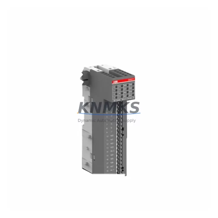
ABB DX571 1TNE968902R2302 Maintenance-Proven Spare for Uptime
The ABB DX571 (part number 1TNE968902R2302) is a digital I/O expansion module engineered for the ABB AC500 PLC platform — one of the most widely deployed programmable logic controller families in process automation, machine control, and critical infrastructure worldwide. As production lines age and original equipment manufacturers phase out legacy support, maintaining a verified stock of the DX571 becomes a cornerstone of any proactive maintenance strategy. Whether you are managing a scheduled annual overhaul, responding to an unplanned fault, or building a resilient spare parts inventory for a multi-line facility, the DX571 is a high-priority line item that directly determines how quickly your control system can be restored to full operation.
This listing supplies the ABB DX571 as an original spare part — pre-shipment tested, compatibility-verified against the AC500 backplane architecture, and backed by a support terms confirmed by quotation. Each unit is dispatched from multi-region stock to support delivery details confirmed by RFQ for both emergency replacements and planned procurement cycles. For maintenance engineers and spare parts buyers operating under tight downtime budgets, this means you receive a unit that is ready to install, not one that requires additional bench testing or firmware alignment before deployment.
Spare Maintenance Table
| Parameter | Specification |
|---|---|
| Part Number | 1TNE968902R2302 |
| Model | DX571 |
| Brand | ABB |
| Series | AC500 |
| Module Type | Digital I/O Expansion Module |
| I/O Configuration | Digital inputs and outputs (DI/DO combined expansion) |
| Backplane Compatibility | AC500 CPU backplane (TB5xx series terminal base) |
| Communication Interface | Internal AC500 expansion bus |
| Supply Voltage | 24 V DC (via terminal base / backplane) |
| Operating Temperature | -25 °C to +60 °C |
| Protection Rating | IP20 (panel-mount, control cabinet installation) |
| Country of Origin | Germany (DE) |
| Weight | Approx. 1,130 g (packaged) |
| Support terms | 12 months from date of shipment |
| Pre-Shipment Test | Yes — functional verification before dispatch |
| Condition | Original spare — new or factory-refurbished to OEM spec |
| Typical Application | Process automation, machine control, building management, utilities |
| Maintenance Recommendation | Inspect terminal base contacts and backplane connector pins during annual overhaul; replace if oxidation or mechanical wear is detected |
Maintenance Planning for Continuous Operation
When a DX571 module is flagged for replacement — whether during a routine point inspection, a fault isolation procedure, or an emergency shutdown — the scope of the maintenance task rarely ends with the module itself. Experienced maintenance engineers know that a digital I/O expansion module sits at the intersection of multiple electrical and signal circuits, and a thorough replacement workflow must account for the health of every connected component.
Begin by verifying the integrity of the AC500 terminal base (TB5xx series) that hosts the DX571. Terminal base contacts are a common source of intermittent faults that are misattributed to the module itself; cleaning or replacing the terminal base before installing the new DX571 eliminates this risk. Next, inspect the 24 V DC power supply rail feeding the I/O bus — voltage ripple or transient spikes are a leading cause of premature module failure and should be measured with a calibrated meter before commissioning the replacement unit.
Check the field wiring and terminal blocks connected to the DX571’s digital inputs and outputs. Loose terminations, corroded conductors, or undersized cable cross-sections can cause signal errors that appear as module faults in the AC500 diagnostic log. If the control cabinet includes signal isolators or optocoupler barriers on high-voltage or long-distance I/O runs, verify their output levels are within the DX571’s input threshold specifications.
For systems where the DX571 interfaces with relay output modules or solid-state relay (SSR) banks, inspect the relay coil drive circuits and load-side fusing. A failed relay or blown fuse on the output side can create misleading diagnostic codes that point to the I/O module rather than the downstream protection component. Similarly, if the AC500 system includes a CP5xx or CP6xx CPU module managing the expansion bus, confirm that the CPU firmware version is compatible with the DX571 hardware revision — firmware mismatches can prevent the module from being recognized after replacement.
Where the control system includes an HMI panel (such as an ABB CP600 or CP400 series) displaying I/O status, update the tag mapping and force-test all affected I/O points after installation to confirm end-to-end signal integrity. Finally, review the system fuse and circuit breaker schedule for the control cabinet — a nuisance trip on the 24 V DC bus during the replacement procedure can indicate an underlying wiring fault that should be resolved before returning the system to automatic operation.
Site Replacement Workflow
Step 1 — Isolate and document. Before removing the DX571, capture the current I/O status from the AC500 CPU diagnostic screen or engineering workstation. Record all active input states and output commands. This baseline is essential for post-replacement verification and reduces the risk of process upsets during commissioning.
Step 2 — De-energize safely. Follow your site’s lockout/tagout (LOTO) procedure for the control cabinet. Disconnect the 24 V DC supply to the I/O bus before removing the DX571 from the terminal base. Do not attempt hot-swap unless the AC500 system configuration explicitly supports it and the process permits it.
Step 3 — Remove and inspect. Slide the DX571 off the terminal base. Inspect the backplane connector on both the module and the terminal base for bent pins, debris, or corrosion. Clean with isopropyl alcohol and a lint-free swab if required. Do not reinstall a damaged terminal base — replace it concurrently to avoid repeat failures.
Step 4 — Install the replacement unit. Seat the new DX571 firmly onto the terminal base until the locking tab engages. Re-energize the 24 V DC bus and observe the module status LED. A solid green LED indicates successful initialization on the AC500 expansion bus. A flashing or red LED indicates a configuration mismatch or hardware fault — consult the AC500 system manual for diagnostic code interpretation.
Step 5 — Verify and recommission. From the engineering workstation or HMI, force-test each digital input and output channel mapped to the DX571. Confirm that field devices respond correctly and that all I/O tags update as expected in the SCADA or DCS historian. Update the maintenance log with the replacement date, part number, and technician sign-off before returning the system to automatic control.
This workflow is designed to minimize mean time to repair (MTTR) and ensure that the replacement DX571 is fully validated before the process resumes — protecting both equipment and production continuity.
Spare Parts Support FAQ
Q1: Is the DX571 (1TNE968902R2302) still available as a new original spare, or only as a refurbished unit?
We supply the DX571 as an original spare — either new old stock (NOS) sourced from authorized distribution channels or factory-refurbished units restored to OEM specification. All units undergo pre-shipment functional testing regardless of condition grade. The condition is confirmed in the shipment documentation accompanying each order.
Q2: How do I confirm compatibility between the DX571 and my existing AC500 CPU and terminal base?
The DX571 is designed for the ABB AC500 expansion bus and is compatible with TB5xx series terminal bases. Compatibility with a specific CPU module (CP5xx or CP6xx series) depends on the firmware version installed on the CPU. We recommend providing your CPU part number and firmware version at the time of inquiry so our technical team can confirm compatibility before shipment. This eliminates the risk of a firmware-related commissioning failure on site.
Q3: What is your lead time for the DX571, and do you hold stock for emergency orders?
We maintain multi-region stock of the DX571 to support both planned procurement and emergency replacement scenarios. Standard orders are typically dispatched within 1–3 business days. For critical plant shutdowns or unplanned outages, contact our sales team directly at admin@knmks.com or +86 18359268345 to confirm real-time stock availability and expedited shipping options.
Q4: What does the support terms confirmed by quotation cover, and what is the process for a support terms claim?
The support terms confirmed by quotation cover manufacturing defects and functional failures under normal operating conditions from the date of shipment. It does not cover damage resulting from incorrect installation, overvoltage events, or unauthorized modification. To initiate a support terms claim, contact our support team with the order reference, a description of the fault, and any available diagnostic data from the AC500 system. We will arrange return logistics and provide a replacement or repair within the agreed service timeline.
© 2026 KNMKS. All rights reserved.
Original Source: https://knmks.com
Contact: admin@knmks.com | +86 18359268345
Product Identification
- Brand / Ecosystem
-
ABB
ABB - Model / Series
-
DX571/1TNE968902R2302
AC500 Series - Product Family
- PLCs & Controllers
- Availability Status
- Available on request after model and quantity confirmation
- Inquiry Type
- B2B RFQ, replacement inquiry and project spare-part request
- Pre-Quote Check
- Exact SKU, brand, series, quantity, nameplate photos and destination country are checked before quotation
System Path
Where this product fits in the KNMKS automation structure.
Specification & Inquiry Focus
- Control platform
- PLC, PAC and modular controllers
- Common needs
- CPU, rack, power and I/O expansion
- Project support
- Replacement, cabinet build and maintenance
Buyer Confirmation
Information KNMKS checks before replying.
- Exact model
- DX571/1TNE968902R2302
- Brand / ecosystem
- ABB
- Product family
- PLCs & Controllers
- Application note
- Replacement, maintenance, project build or spare-part list
- Useful photos
- Nameplate, installed unit, cabinet layout or connector side
- Delivery details
- Quantity, destination country and target schedule
Document Support
Files and notes can be confirmed during quotation.
- Product photos or nameplate confirmation when available
- Packing and delivery notes before quotation confirmation
- Support scope and delivery terms confirmed per inquiry
- Export document coordination for qualified B2B requests
Inquiry Support
- Model cross-checking before quotation
- CPU, power, rack and expansion module matching
- Support for replacement and project inquiry
What to Send Us
- Brand and exact model number: ABB DX571/1TNE968902R2302
- Quantity and required delivery time
- Application, replacement requirement or nameplate photo
- Destination country and shipping preference
RFQ Preparation
This is a product inquiry page built for RFQ communication.
Fast Model Check
Send this model to KNMKS for confirmation.
Include quantity, destination country and photos if this is a maintenance replacement. The inquiry will be saved with a reference number after submission.
Brand & Compatibility Note
KNMKS displays automation product information for well-known industrial brand ecosystems and compatible replacement references. Brand names are used for product identification and compatibility reference only; final availability and commercial terms are confirmed per quotation.
 Manufacturing
 Machine Tools
 Packaging
 Energy & Power
 HMI & Displays
 Servo Systems
 Variable Frequency Drives
 Sensors