
Overview
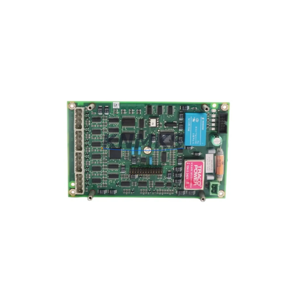
ABB DATX130 3ASC25H214 Migration-Ready Rotor Feedback Board for Legacy Control Systems
The ABB DATX130 (3ASC25H214) is a rotor feedback board designed for ABB DRIVETEC series AC variable-speed drives. As legacy DRIVETEC installations age beyond their original service life, this board has become a critical spare part for engineers managing retrofit projects, unplanned drive failures, and planned system modernization programs. Whether you are replacing a failed unit in an existing cabinet or executing a phased upgrade of an older drive platform, the DATX130 provides a verified drop-in solution that preserves your existing wiring topology and minimizes engineering rework.
In retrofit scenarios, the DATX130 interfaces directly with the drive’s rotor position sensing circuit, providing accurate speed and position feedback to the main control board. Before installation, engineers should confirm the feedback signal type (resolver or encoder), verify the terminal block pinout against the existing field wiring, and check that the backplane connector on the drive chassis is undamaged. The board is compatible with the standard DRIVETEC rack form factor, so installation space is typically not a concern when replacing a like-for-like unit. However, if the surrounding drive assembly has been modified or if adjacent boards such as the DSMB-01C pulse encoder interface module or the SDCS-CON-4 control board have already been upgraded, firmware version alignment should be confirmed before commissioning.
For sites running older DRIVETEC cabinets alongside newer ACS800 or ACS880 drive platforms, the DATX130 serves as a bridge component that allows the legacy drive to remain operational while the broader migration is planned in stages. This approach is common in continuous-process industries where a full drive replacement cannot be scheduled without a planned shutdown window. By restoring the rotor feedback function with a verified replacement board, maintenance teams can extend the operational life of the existing drive by 12 to 36 months, providing the planning time needed to procure replacement drives, update HMI screens, and retrain operators.
When preparing for installation, the following checklist covers the most common verification points encountered during DATX130 replacement projects:
- Power supply capacity: Confirm the internal 24 VDC auxiliary supply rail can support the additional board load without tripping the drive’s internal power fault.
- Terminal wiring: Map existing field cables against the DATX130 terminal layout. Pay particular attention to shield grounding and differential signal pairs to avoid noise-induced feedback errors.
- Backplane interface: Inspect the drive backplane connector for bent pins or corrosion before seating the replacement board.
- Module addressing: If the drive uses a multi-board architecture with a DPCB-01 parameter backup unit or similar configuration memory device, verify that module slot addressing is preserved after board swap.
- Program compatibility: Confirm that the existing drive application program does not reference board-specific firmware parameters that differ between DATX130 hardware revisions.
- HMI screens: If a local operator panel or remote HMI is connected via the drive’s fieldbus interface, verify that speed feedback display values are within expected range after the board is installed and the drive is powered up.
- Communication links: For drives integrated into a PROFIBUS DP or Modbus RTU network, confirm that the communication adapter — such as an RPBA-01 PROFIBUS adapter — remains correctly addressed and that the PLC receives valid drive status words after the replacement.
- Firmware version: Cross-reference the DATX130 hardware revision marking against the drive’s firmware release notes to confirm compatibility.
- Commissioning procedure: After installation, perform a no-load motor run to verify feedback signal integrity before reconnecting the mechanical load.
Migration Compatibility Table
| Parameter | Details |
|---|---|
| Part Number | DATX130 / 3ASC25H214 |
| Brand | ABB |
| Series | DRIVETEC |
| Function | Rotor Feedback Board |
| Compatible Drive Platform | ABB DRIVETEC AC Variable-Speed Drives |
| Backplane Interface | Standard DRIVETEC rack connector |
| Feedback Signal Type | Resolver / Rotor position sensing |
| Installation Form Factor | Drop-in replacement, standard DRIVETEC board slot |
| Communication Compatibility | Compatible with PROFIBUS DP, Modbus RTU via drive adapter |
| Replacement Recommendation | Direct replacement for failed or degraded DATX130 units in legacy DRIVETEC cabinets |
| Commissioning Note | Verify firmware revision and perform no-load test run before reconnecting load |
| Origin | Germany |
| Support terms | support terms confirmed by quotation |
| Availability | availability confirmed by RFQ — Ready to Ship |
Retrofit Planning for Existing Automation Systems
Successful DATX130 retrofit projects rarely involve the feedback board in isolation. In most DRIVETEC cabinet upgrades, the rotor feedback board replacement is one step in a broader sequence that also addresses the drive’s power supply integrity, I/O wiring, and network connectivity. Engineers frequently find that a failed DATX130 is accompanied by degraded performance in adjacent components, making it practical to inspect and, where necessary, replace related boards during the same maintenance window.
Common components addressed during DRIVETEC retrofit projects alongside the DATX130 include the DSMB-01C pulse encoder interface module for sites using incremental encoder feedback, the SDCS-CON-4 DC drive control board where mixed AC/DC drive architectures exist in the same control room, and the RPBA-01 PROFIBUS DP adapter for drives integrated into plant-wide PLC networks. For cabinets where the internal 24 VDC power supply has been running beyond its rated service life, replacement of the SDCS-POW-4 power supply board is often scheduled concurrently to avoid a repeat shutdown within the same maintenance cycle. Where the drive communicates with a Siemens S7 or Allen-Bradley ControlLogix PLC via a fieldbus gateway, the NMBP-01 Modbus Plus adapter may also require reconfiguration after the board swap to restore correct drive status reporting to the supervisory system.
For sites planning a longer-term migration from DRIVETEC to a current-generation ABB drive platform, the DATX130 replacement provides an opportunity to document the existing wiring, parameter settings, and control logic before the full drive replacement is executed. This documentation step significantly reduces commissioning time when the new drive is installed and reduces the risk of undocumented field modifications causing unexpected behavior during startup.
Downtime Control During System Migration
Minimizing unplanned downtime is the primary concern for maintenance engineers managing DATX130 replacements in production environments. The board’s drop-in form factor means that a prepared technician with the correct replacement unit can complete the physical swap in under 30 minutes, provided the drive has been safely isolated and the terminal wiring has been documented in advance. The most common source of extended downtime during DATX130 replacements is not the physical installation but the post-installation verification process — particularly when the drive’s parameter set has not been backed up and must be reconstructed from plant documentation or from the PLC program.
To protect the original control logic and minimize commissioning risk, the following practices are recommended before the drive is taken offline: export the full drive parameter set using the drive’s keypad or a connected PC tool, photograph or sketch the existing terminal wiring, and confirm with the control room that the PLC program’s drive interface logic is documented and accessible. Where a DPCB-01 parameter backup unit is installed in the drive, verify that the stored parameter set reflects the current running configuration before the board swap begins.
After the DATX130 is installed and the drive is powered up, the recommended commissioning sequence is: restore the parameter set, perform an ID run if the motor data has changed, verify feedback signal quality at no load, confirm PLC communication is re-established, and perform a supervised loaded test run before returning the drive to automatic control. Following this sequence consistently across all DRIVETEC retrofit projects reduces the average commissioning time and ensures that the support terms confirmed by quotation period begins from a verified, correctly commissioned installation.
Retrofit Support FAQ
Q1: Is the DATX130 3ASC25H214 a direct replacement for all DRIVETEC rotor feedback board variants?
The DATX130 with part reference 3ASC25H214 is the standard rotor feedback board for the DRIVETEC AC drive series. Before ordering, confirm the hardware revision marking on the existing board and cross-reference against the drive’s spare parts list to ensure the replacement unit matches the required revision level. Our team can assist with revision verification if you provide the drive’s serial number or nameplate data.
Q2: What wiring checks are required before installing the replacement board?
Before installation, verify the resolver cable shield continuity, confirm that the terminal block screws on the existing board are not corroded or damaged, and check that the differential signal pairs are correctly identified in the field wiring documentation. Incorrect shield grounding is the most common cause of feedback noise faults after a board replacement.
Q3: How is the board tested before shipment?
All DATX130 units supplied by KNMKS are function-tested prior to dispatch. Each board undergoes power-on verification and signal output checks. A test report is available on request. The support terms confirmed by quotation cover manufacturing defects and verified functional failures under normal operating conditions.
Q4: What is the typical lead time and do you hold stock?
The DATX130 3ASC25H214 is held availability confirmed by RFQ and is available for immediate dispatch. Standard international shipping lead times apply depending on destination. For urgent requirements, expedited shipping options are available. Contact our sales team at admin@knmks.com or +86 18359268345 to confirm current stock levels and shipping options.
© 2026 KNMKS. All rights reserved.
Original Source: https://knmks.com
Contact: admin@knmks.com | +86 18359268345
Product Identification
- Brand / Ecosystem
-
ABB
ABB - Model / Series
- DATX130 3ASC25H214
- Product Family
- PLCs & Controllers
- Availability Status
- Available on request after model and quantity confirmation
- Inquiry Type
- B2B RFQ, replacement inquiry and project spare-part request
- Pre-Quote Check
- Exact SKU, brand, series, quantity, nameplate photos and destination country are checked before quotation
System Path
Where this product fits in the KNMKS automation structure.
Specification & Inquiry Focus
- Control platform
- PLC, PAC and modular controllers
- Common needs
- CPU, rack, power and I/O expansion
- Project support
- Replacement, cabinet build and maintenance
Buyer Confirmation
Information KNMKS checks before replying.
- Exact model
- DATX130 3ASC25H214
- Brand / ecosystem
- ABB
- Product family
- PLCs & Controllers
- Application note
- Replacement, maintenance, project build or spare-part list
- Useful photos
- Nameplate, installed unit, cabinet layout or connector side
- Delivery details
- Quantity, destination country and target schedule
Document Support
Files and notes can be confirmed during quotation.
- Product photos or nameplate confirmation when available
- Packing and delivery notes before quotation confirmation
- Support scope and delivery terms confirmed per inquiry
- Export document coordination for qualified B2B requests
Inquiry Support
- Model cross-checking before quotation
- CPU, power, rack and expansion module matching
- Support for replacement and project inquiry
What to Send Us
- Brand and exact model number: ABB DATX130 3ASC25H214
- Quantity and required delivery time
- Application, replacement requirement or nameplate photo
- Destination country and shipping preference
RFQ Preparation
This is a product inquiry page built for RFQ communication.
Fast Model Check
Send this model to KNMKS for confirmation.
Include quantity, destination country and photos if this is a maintenance replacement. The inquiry will be saved with a reference number after submission.
Brand & Compatibility Note
KNMKS displays automation product information for well-known industrial brand ecosystems and compatible replacement references. Brand names are used for product identification and compatibility reference only; final availability and commercial terms are confirmed per quotation.
 Manufacturing
 Machine Tools
 Packaging
 Energy & Power
 HMI & Displays
 Servo Systems
 Variable Frequency Drives
 Sensors