
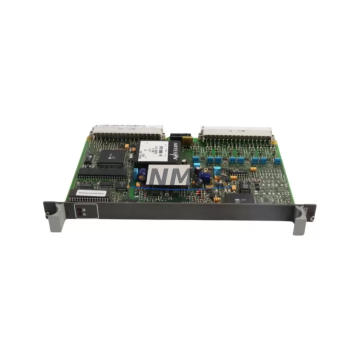
Overview
ABB 81AA03aA-E Migration-Ready Digital Output for AC500: Legacy System Retrofit & Compatibility Upgrade
The ABB 81AA03aA-E is a digital output module designed for the ABB AC500 programmable logic controller platform, widely deployed across process automation, machine control, and utility infrastructure projects. As legacy AC500 installations age and original spare parts enter end-of-life or allocation-constrained supply cycles, the 81AA03aA-E has become a critical migration-ready replacement for engineers managing control cabinet upgrades, I/O expansion, and system continuity programs. This module supports direct drop-in installation on compatible AC500 backplanes, preserving existing terminal wiring layouts and minimizing the engineering effort required during retrofit campaigns.
When planning a replacement for a discontinued or hard-to-source digital output module in an AC500 rack, engineers must verify several key parameters before committing to a swap. Power supply capacity at the backplane level is the first checkpoint — the 81AA03aA-E draws from the rack’s internal bus, and the existing PM5xx or PM5xx-ETH CPU module’s power budget must accommodate the module’s load alongside any co-installed analog or communication modules. Terminal wiring compatibility is equally important: the 81AA03aA-E uses a standard 40-pin front connector arrangement consistent with the AC500 I/O family, allowing existing field cables to be reconnected without re-termination in most retrofit scenarios.
Backplane slot addressing must be confirmed in the Automation Builder or PS501 Control Builder programming environment before the module is inserted. The AC500 system assigns I/O addresses based on physical slot position, and any change in slot assignment relative to the original module layout will require a corresponding update to the PLC program’s I/O mapping table. In projects where the original program source code is unavailable, engineers should perform an online upload from the running CPU — typically a PM554, PM564, or PM583 — before the shutdown window begins, ensuring the logic can be re-downloaded after the hardware swap without loss of configuration data.
HMI screen updates are a frequently overlooked step in digital output module replacements. If the plant’s SCADA or HMI system — whether running on ABB’s CP600 operator panel series or a third-party visualization platform — references specific output channel tags tied to the replaced module, those tag bindings must be validated post-swap. Communication link integrity between the CPU and any co-installed communication modules such as the CM572-DP PROFIBUS master or CM589-PNIO PROFINET interface module should also be confirmed during commissioning, as a rack power cycle during module replacement can occasionally reset communication parameters on older firmware versions.
Installation space confirmation is straightforward for like-for-like replacements within the same AC500 rack generation, but becomes a planning item when the retrofit involves migrating from an older S500 I/O generation to the current AC500 I/O family. In mixed-generation cabinets, the physical depth of the new module and the routing space for front connector cables must be assessed against the existing cabinet layout. Firmware version alignment between the 81AA03aA-E and the host CPU should be checked against ABB’s compatibility matrix — modules shipped from current stock are typically pre-loaded with firmware compatible with AC500 V2 and V3 CPU generations, but field verification using Automation Builder’s device catalog is recommended before the maintenance window.
On-site commissioning after installation involves forcing individual output channels in test mode to verify field device response, confirming that load current per channel remains within the module’s rated output capacity, and checking that the CPU’s diagnostic buffer does not log any module configuration mismatch errors. These steps are particularly important when the 81AA03aA-E is being introduced into a system that previously ran a different output module variant, as channel count or output voltage range differences between variants can affect field device behavior if not accounted for in the program logic.
Migration Compatibility Table
| Parameter | Detail |
|---|---|
| Module SKU | ABB 81AA03aA-E |
| Series / Platform | ABB AC500 PLC I/O Family |
| Module Type | Digital Output Module |
| Backplane Interface | AC500 I/O bus — compatible with TB521, TB541, TB561 terminal base units |
| Front Connector | 40-pin standard AC500 I/O front connector; existing field wiring reusable in most cases |
| Compatible CPUs | PM554, PM564, PM572, PM583, PM591, PM592 (AC500 V2 / V3) |
| Communication Compatibility | PROFIBUS (CM572-DP), PROFINET (CM589-PNIO), Modbus TCP — no protocol reconfiguration required for like-for-like swap |
| Programming Environment | ABB Automation Builder / PS501 Control Builder; I/O address re-mapping required if slot position changes |
| Installation Requirement | Confirm rack power budget; verify slot address assignment before insertion |
| Firmware Compatibility | Compatible with AC500 V2 and V3 firmware generations; verify via Automation Builder device catalog |
| Replacement Recommendation | Direct drop-in for same-series digital output modules; confirm channel count and output voltage range match |
| Commissioning Focus | Force-test output channels; check CPU diagnostic buffer for configuration mismatch errors |
| Origin | Germany (DE) |
| Support terms | support terms confirmed by quotation — covers manufacturing defects; pre-shipment functional test included |
Retrofit Planning for Existing Automation Systems
A successful retrofit of the ABB 81AA03aA-E into an existing AC500 installation typically begins with a full rack audit. Engineers should document the current slot population — noting the position of the CPU module (commonly a PM564 or PM583), any installed communication modules such as the CM572-DP for PROFIBUS networks or the CM589-PNIO for PROFINET-connected systems, and the arrangement of existing digital and analog I/O modules. This audit forms the baseline for the replacement plan and helps identify whether adjacent modules will be disturbed during the swap.
Power supply sizing is a recurring concern in retrofit projects. The AC500 rack’s internal bus power is distributed from the CPU module, and adding or replacing I/O modules can shift the total bus load. If the existing installation is running close to the CPU’s rated bus current output, the addition of the 81AA03aA-E may require a review of the power distribution architecture — in some cases, an auxiliary power supply module or a redistribution of modules across multiple racks may be warranted. Terminal base units such as the TB521 or TB541 should be inspected for contact wear if they have been in service for extended periods, as degraded terminal contacts can cause intermittent output channel faults that are difficult to distinguish from module-level failures.
For installations that include signal isolators between the PLC output channels and field devices — a common practice in hazardous area or high-noise industrial environments — the isolator input specifications must be re-confirmed against the 81AA03aA-E’s output characteristics. Similarly, if the control cabinet includes an ABB CP600 series HMI panel for local operator interaction, the panel’s tag database should be reviewed to ensure that output channel references remain valid after the module swap. Programming cables and USB-to-serial adapters used for on-site Automation Builder connections should be tested before the maintenance window to avoid delays during the commissioning phase.
Downtime Control During System Migration
Minimizing unplanned downtime during a digital output module replacement in an AC500 system requires a structured pre-shutdown checklist. Before the maintenance window opens, the engineer should perform a full online backup of the CPU program — including the I/O configuration, variable table, and any retain variable values — using Automation Builder’s project upload function. This backup ensures that if the CPU loses its program during the power cycle associated with the module swap, the logic can be restored within minutes rather than hours.
The physical replacement of the 81AA03aA-E is a hot-swap-aware process on AC500 racks that support I/O module replacement under power, but this capability depends on the specific CPU firmware version and rack configuration. Engineers should confirm hot-swap support in the system documentation before attempting a live replacement; if hot-swap is not supported or not confirmed, a controlled shutdown of the affected rack section is the safer approach. Field device outputs should be placed in a safe state — typically de-energized — before the module is removed, and the control room operator should be informed of the expected output interruption window.
After the 81AA03aA-E is seated and the rack is powered, the CPU should be allowed to complete its startup diagnostic cycle before the program is set to RUN mode. The Automation Builder diagnostic buffer should be checked for any module recognition errors or I/O configuration mismatches. Once the module is confirmed online, individual output channels should be force-tested from the programming environment to verify field device response before returning the system to automatic control. This structured commissioning sequence typically allows a like-for-like digital output module replacement to be completed within a two-to-four hour maintenance window, including pre-shutdown preparation and post-swap verification.
Retrofit Support FAQ
Q: Is the ABB 81AA03aA-E a direct replacement for other AC500 digital output modules?
A: The 81AA03aA-E is designed for the AC500 I/O platform and is compatible with AC500 terminal base units and backplane bus architecture. For a confirmed like-for-like replacement, verify that the channel count, output voltage range, and current rating of the 81AA03aA-E match the module being replaced. In cases where the original module variant is discontinued, the 81AA03aA-E may serve as a functional equivalent subject to minor program I/O mapping adjustments.
Q: What commissioning steps are required after installing the 81AA03aA-E?
A: After seating the module and powering the rack, confirm module recognition in Automation Builder, check the CPU diagnostic buffer for configuration errors, verify I/O address assignments match the program configuration, and force-test each output channel to confirm field device response. If the slot position has changed relative to the original module, update the I/O mapping in the PLC program before setting the CPU to RUN mode.
Q: Can the existing field wiring be reused when installing the 81AA03aA-E?
A: In most like-for-like replacement scenarios within the AC500 I/O family, the existing 40-pin front connector and field wiring can be reused without re-termination. However, engineers should inspect terminal contacts for wear or corrosion, particularly in installations that have been in service for more than five years, and confirm that the wiring gauge and insulation rating are compatible with the 81AA03aA-E’s terminal specifications.
Q: What support terms and pre-shipment testing does the 81AA03aA-E include?
A: Every ABB 81AA03aA-E unit supplied by KNMKS includes a support terms confirmed by quotation covering manufacturing defects and functional failures under normal operating conditions. Each unit undergoes a pre-shipment functional test to verify output channel operation before dispatch. Global stock is maintained to support urgent replacement requirements, with expedited shipping options available for critical maintenance situations.
© 2026 KNMKS. All rights reserved.
Original Source: https://knmks.com
Contact: admin@knmks.com | +86 18359268345
Product Identification
- Brand / Ecosystem
-
ABB
ABB - Model / Series
-
81AA03aA-E
AC500 Series - Product Family
- PLCs & Controllers
- Availability Status
- Available on request after model and quantity confirmation
- Inquiry Type
- B2B RFQ, replacement inquiry and project spare-part request
- Pre-Quote Check
- Exact SKU, brand, series, quantity, nameplate photos and destination country are checked before quotation
System Path
Where this product fits in the KNMKS automation structure.
Specification & Inquiry Focus
- Control platform
- PLC, PAC and modular controllers
- Common needs
- CPU, rack, power and I/O expansion
- Project support
- Replacement, cabinet build and maintenance
Buyer Confirmation
Information KNMKS checks before replying.
- Exact model
- 81AA03aA-E
- Brand / ecosystem
- ABB
- Product family
- PLCs & Controllers
- Application note
- Replacement, maintenance, project build or spare-part list
- Useful photos
- Nameplate, installed unit, cabinet layout or connector side
- Delivery details
- Quantity, destination country and target schedule
Document Support
Files and notes can be confirmed during quotation.
- Product photos or nameplate confirmation when available
- Packing and delivery notes before quotation confirmation
- Support scope and delivery terms confirmed per inquiry
- Export document coordination for qualified B2B requests
Inquiry Support
- Model cross-checking before quotation
- CPU, power, rack and expansion module matching
- Support for replacement and project inquiry
What to Send Us
- Brand and exact model number: ABB 81AA03aA-E
- Quantity and required delivery time
- Application, replacement requirement or nameplate photo
- Destination country and shipping preference
RFQ Preparation
This is a product inquiry page built for RFQ communication.
Fast Model Check
Send this model to KNMKS for confirmation.
Include quantity, destination country and photos if this is a maintenance replacement. The inquiry will be saved with a reference number after submission.
Brand & Compatibility Note
KNMKS displays automation product information for well-known industrial brand ecosystems and compatible replacement references. Brand names are used for product identification and compatibility reference only; final availability and commercial terms are confirmed per quotation.
 Manufacturing
 Machine Tools
 Packaging
 Energy & Power
 HMI & Displays
 Servo Systems
 Variable Frequency Drives
 Sensors