
Overview
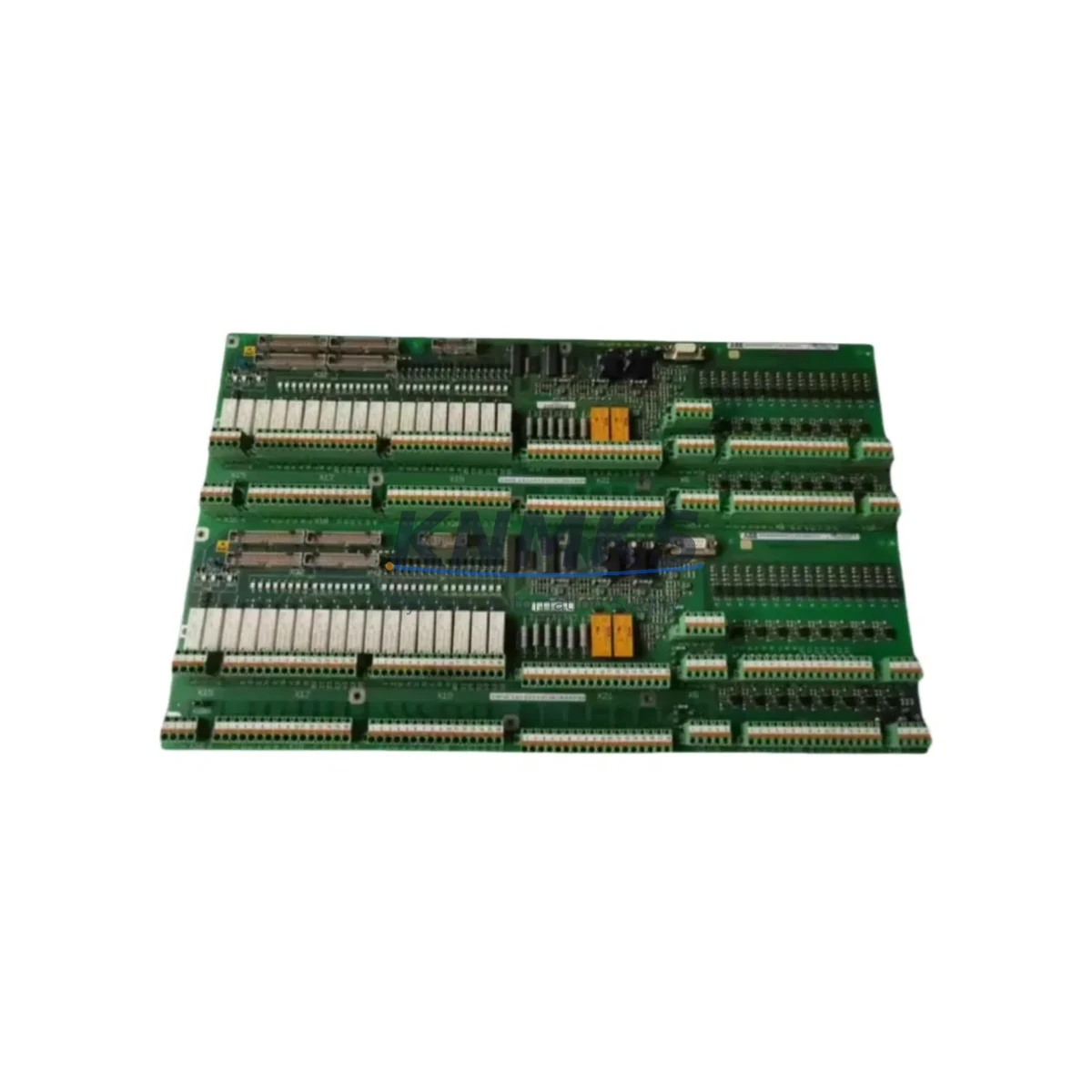
ABB 3BHB007437P0002 Migration-Ready VFD Module for Legacy ACS6000 Control Systems
The ABB 3BHB007437P0002 (M3V10-7/0-0 YYN0) is a migration-ready Variable Frequency Drive (VFD) module engineered for the ACS6000 M3V Series medium-voltage drive platform. As legacy ACS6000 installations approach end-of-service milestones and original ABB spare parts enter allocation constraints or discontinuation cycles, this module provides a verified drop-in replacement path that preserves existing cabinet architecture, backplane wiring, and drive control logic without requiring a full system redesign.
Designed for critical industrial applications including large motor drives in mining, oil & gas, marine propulsion, metals processing, and power generation, the 3BHB007437P0002 maintains full electrical and mechanical compatibility with the ACS6000 M3V drive family. Engineers planning a retrofit or emergency replacement can rely on this module to restore drive functionality with minimal disruption to the existing control hierarchy.
Each unit is sourced from verified supply channels, subjected to pre-shipment functional testing, and backed by a support terms confirmed by quotation covering manufacturing defects and operational failures under normal service conditions. Global shipping with export documentation is available for international maintenance programs.
Migration Compatibility Table
| Parameter | Specification / Retrofit Guidance |
|---|---|
| Part Number | 3BHB007437P0002 |
| Module Designation | M3V10-7/0-0 YYN0 |
| Platform Compatibility | ABB ACS6000 M3V Series Medium-Voltage VFD |
| Replacement Target | Legacy 3BHB007437P0001 and equivalent M3V10 variants (verify suffix before ordering) |
| Backplane Interface | ACS6000 standard backplane slot — confirm rack generation (Gen 1 vs Gen 2) before installation |
| Communication Protocol | DDCS (Distributed Drive Control System) fiber-optic link; compatible with RDCO-02/03 communication adapters |
| Power Supply Requirement | Verify internal DC bus voltage and auxiliary 24 VDC supply capacity before module swap |
| Terminal Wiring | Retain existing signal and power terminal assignments; re-torque all connections post-installation |
| Firmware Compatibility | Confirm ACS6000 drive firmware version; module may require parameter restore from backup dataset |
| Installation Space | Standard ACS6000 module bay; verify clearance for cooling airflow and fiber-optic cable routing |
| Commissioning Requirement | Parameter upload from DriveWindow or DriveWindow Light; motor ID run recommended after replacement |
| Pre-Shipment Testing | Functional test performed; test report available on request |
| Support terms | 12 months from date of shipment |
Retrofit Planning for Existing Automation Systems
A successful ACS6000 retrofit begins well before the replacement module arrives on site. Maintenance teams should start by auditing the full drive cabinet configuration, including the AINT-02 or AINT-14 inverter control board, the APBU-44C pulse encoder interface unit, and any installed RDCO-02 DDCS communication adapter. These components interact directly with the M3V10-7/0-0 YYN0 module and must be confirmed operational before the swap to avoid misdiagnosis of post-replacement faults.
For sites running the ACS6000 in a multi-drive configuration with a shared DDCS fiber ring, the NDBU-95 branching unit should be inspected for optical signal integrity. A degraded fiber link can cause the replacement module to report communication faults that are unrelated to the module itself, adding unnecessary troubleshooting time during a planned outage window.
Power capacity verification is critical. The 3BHB007437P0002 operates within the ACS6000 DC bus architecture, and the upstream transformer and rectifier section must be confirmed capable of supporting the module’s rated load. If the site has added motor loads since the original commissioning, a power audit should be completed before the retrofit to avoid nuisance tripping post-installation.
Terminal wiring should be documented with photographs before disconnection. The ACS6000 M3V Series uses a structured terminal block layout, and any deviation from the original wiring diagram — particularly on the analog I/O and digital I/O signal terminals — can cause unexpected behavior during the first motor start. Where the original wiring documentation is incomplete, the ABB ACS6000 Hardware Manual (3AFE64590430) provides the reference terminal assignment tables.
HMI integration should also be validated. Sites using ABB Panel Bus or Modbus RTU connections to a local operator panel will need to confirm that the replacement module’s parameter set restores the correct drive reference and feedback scaling. If the site uses a third-party SCADA system with OPC-DA or OPC-UA connectivity, the tag mapping should be verified against the restored parameter dataset before returning the drive to automatic control mode.
For sites with limited spare parts inventory, it is advisable to stock the AGPS-21C gate driver power supply board and the APOW-01 auxiliary power supply module alongside the 3BHB007437P0002. These components are frequently identified as secondary failure points during ACS6000 unplanned outages and having them available on-site significantly reduces mean time to repair.
Downtime Control During System Migration
Minimizing downtime during an ACS6000 module replacement requires a structured pre-outage preparation protocol. Before the planned maintenance window opens, the drive’s full parameter dataset should be backed up using DriveWindow or DriveWindow Light software connected via the RDCO-02 DDCS adapter or the drive’s front panel USB port if available. This backup preserves motor nameplate data, speed reference scaling, protection relay settings, and any application-specific macro configurations that would otherwise require manual re-entry after the module swap.
The original control program logic — particularly any application blocks configured through the ACS6000’s internal application programming interface — should be exported and stored in a version-controlled file. This protects against accidental parameter overwrite during the module initialization sequence and allows rapid restoration if the commissioning engineer needs to roll back to a known-good configuration.
During the physical swap, the DDCS fiber-optic cables connecting the M3V module to the NDBU branching unit should be handled with care. Fiber connectors should be cleaned with an appropriate optical cleaning tool before reconnection to prevent signal attenuation that can cause intermittent communication faults after restart. Cable routing should follow the original path to avoid mechanical stress on the connectors.
After installation, the recommended commissioning sequence is: power-on self-test, parameter restore from backup, motor identification run at reduced load, and a supervised ramp-to-speed test before returning the drive to process control. This sequence typically requires two to four hours for a prepared maintenance team, keeping the total outage window within a single planned maintenance shift. Sites with 24/7 production schedules should coordinate the replacement with process control to arrange a controlled process hold rather than an emergency shutdown, which significantly reduces the risk of secondary equipment damage.
All replacement activities should be logged in the site’s maintenance management system with the module serial number, installation date, and commissioning engineer’s sign-off. This record supports the support terms confirmed by quotation claim process and provides traceability for future audits or insurance assessments.
Retrofit Support FAQ
Q1: Is the 3BHB007437P0002 a direct drop-in replacement for the 3BHB007437P0001?
The P0002 suffix indicates a revision update to the P0001. In most ACS6000 M3V10 installations, the P0002 is backward compatible, but the drive firmware version should be confirmed before installation. ABB recommends verifying the hardware revision compatibility matrix in the ACS6000 service documentation or contacting our technical team with your drive serial number for a definitive compatibility confirmation.
Q2: What commissioning tools are required after replacing this module?
DriveWindow 2 or DriveWindow Light is required for parameter upload and motor ID run. A laptop with a compatible DDCS or USB interface cable, the backed-up parameter file, and the motor nameplate data are the minimum requirements. On-site commissioning support documentation is available upon request.
Q3: Can this module be installed without shutting down the entire drive cabinet?
No. The 3BHB007437P0002 is a live-bus module and must only be installed with the ACS6000 main circuit de-energized and locked out per site LOTO procedures. Attempting a hot-swap will damage the module and may create a safety hazard. Full cabinet de-energization and a minimum 5-minute DC bus discharge wait period are required before module removal.
Q4: What does the support terms confirmed by quotation cover, and how is a claim initiated?
The support terms confirmed by quotation cover manufacturing defects and operational failures under normal operating conditions as defined in the ACS6000 technical specification. It does not cover damage resulting from incorrect installation, overvoltage events, or operation outside rated parameters. To initiate a support terms claim, contact admin@knmks.com with the module serial number, installation date, fault description, and any available drive fault log data. Replacement or repair will be arranged within the agreed service timeline.
© 2026 KNMKS. All rights reserved.
Original Source: https://knmks.com
Contact: admin@knmks.com | +86 18359268345
Product Identification
- Brand / Ecosystem
-
ABB
ABB - Model / Series
- M3V10-7/0-0 YYN0 3BHB007437P0002
- Product Family
- Variable Frequency Drives
- Availability Status
- Available on request after model and quantity confirmation
- Inquiry Type
- B2B RFQ, replacement inquiry and project spare-part request
- Pre-Quote Check
- Exact SKU, brand, series, quantity, nameplate photos and destination country are checked before quotation
System Path
Where this product fits in the KNMKS automation structure.
Specification & Inquiry Focus
- Drive range
- AC drives, VFDs and accessories
- Common needs
- Voltage, kW/HP and load type
- Project support
- Motor control, energy saving and spares
Buyer Confirmation
Information KNMKS checks before replying.
- Exact model
- M3V10-7/0-0 YYN0 3BHB007437P0002
- Brand / ecosystem
- ABB
- Product family
- Variable Frequency Drives
- Application note
- Replacement, maintenance, project build or spare-part list
- Useful photos
- Nameplate, installed unit, cabinet layout or connector side
- Delivery details
- Quantity, destination country and target schedule
Document Support
Files and notes can be confirmed during quotation.
- Product photos or nameplate confirmation when available
- Packing and delivery notes before quotation confirmation
- Support scope and delivery terms confirmed per inquiry
- Export document coordination for qualified B2B requests
Inquiry Support
- Input/output voltage and kW/HP confirmation
- Energy-saving motor control inquiry
- Accessory and spare-unit support
What to Send Us
- Brand and exact model number: ABB M3V10-7/0-0 YYN0 3BHB007437P0002
- Quantity and required delivery time
- Application, replacement requirement or nameplate photo
- Destination country and shipping preference
RFQ Preparation
This is a product inquiry page built for RFQ communication.
Fast Model Check
Send this model to KNMKS for confirmation.
Include quantity, destination country and photos if this is a maintenance replacement. The inquiry will be saved with a reference number after submission.
Brand & Compatibility Note
KNMKS displays automation product information for well-known industrial brand ecosystems and compatible replacement references. Brand names are used for product identification and compatibility reference only; final availability and commercial terms are confirmed per quotation.
 Manufacturing
 Machine Tools
 Packaging
 Energy & Power
 PLCs & Controllers
 HMI & Displays
 Servo Systems
 Sensors