
Overview
Allen-Bradley 2198-P070 Maintenance-Proven Spare Part for Factory Uptime
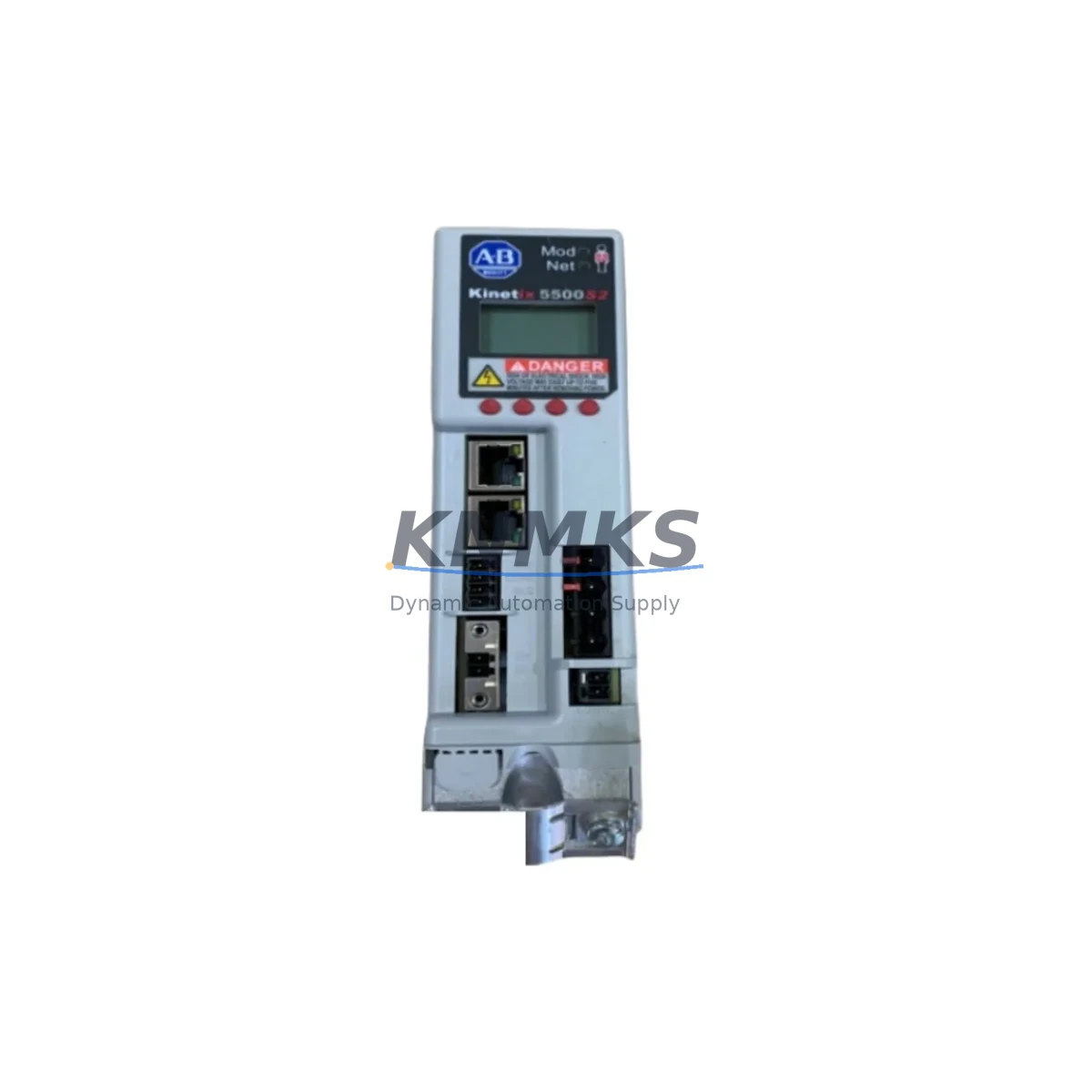
The Allen-Bradley 2198-P070 is a 70 kW Shared DC Bus Power Supply designed for the Kinetix 5500 servo drive system. As a critical power infrastructure component in multi-axis motion control architectures, this unit supplies regulated DC bus voltage to multiple Kinetix 5500 axis modules operating in a shared bus configuration. Maintaining a verified spare of the 2198-P070 in your parts inventory is a proven strategy for minimizing unplanned downtime in high-throughput manufacturing environments, packaging lines, material handling systems, and precision assembly cells.
For maintenance engineers managing Kinetix 5500 installations, the 2198-P070 sits at the heart of the DC bus distribution network. A failure in this unit will immediately cascade across all connected axis modules, halting multi-axis coordinated motion and triggering system-wide faults. Rapid replacement with a pre-tested, original spare is the most reliable path to production recovery. Our 2198-P070 units are sourced from authorized channels, subjected to pre-shipment functional testing, and backed by a support terms confirmed by quotation — ensuring you receive a field-ready component, not a shelf-aged unknown.
Spare Maintenance Table
| Parameter | Specification |
|---|---|
| Part Number | 2198-P070 |
| Brand | Allen-Bradley (Rockwell Automation) |
| Series | Kinetix 5500 |
| Type | Shared DC Bus Power Supply |
| Rated Output Power | 70 kW |
| Input Voltage | 195–528 VAC, 3-phase |
| DC Bus Output Voltage | Approx. 650–750 VDC (line dependent) |
| Cooling Method | Forced air (internal fan) |
| Mounting | Panel mount, DIN rail compatible enclosure |
| Communication | Integrated with Kinetix 5500 axis modules via shared bus connector |
| Compatibility | Kinetix 5500 axis modules (2198-Hxxx series) |
| Application Environment | Industrial control panels, servo drive cabinets, motion control enclosures |
| Operating Temperature | 0–50°C (32–122°F) |
| Origin | USA |
| Support terms | 12 Months — Pre-shipment tested, functional verification included |
Maintenance Planning for Continuous Operation
When planning a replacement or scheduled maintenance intervention involving the 2198-P070, maintenance and procurement engineers should treat this as a system-level event rather than a single-component swap. The shared DC bus architecture means that the power supply interfaces directly with every axis module in the drive group. Before or during replacement, the following associated components should be inspected and verified:
AC Input and Power Distribution: Inspect the upstream 3-phase AC input wiring, terminal blocks, and input fusing or circuit breakers feeding the 2198-P070. Loose connections or degraded terminals at the input stage are a common root cause of premature power supply failure. Verify that the AC line voltage is within the 195–528 VAC specification under load conditions.
Kinetix 5500 Axis Modules (2198-Hxxx): Each axis module connected to the shared DC bus should be inspected for fault history, thermal stress indicators, and connector integrity. A failed or degraded axis module can impose abnormal loads on the DC bus, potentially contributing to power supply stress. Replacing the 2198-P070 without auditing the axis modules risks repeat failure.
DC Bus Capacitor Bank and Discharge Resistors: In shared bus configurations, the DC bus capacitor bank (internal to the power supply and distributed across axis modules) should be evaluated for capacitance degradation, especially in systems with high cycle rates or frequent regenerative braking events. Discharge resistors and pre-charge circuits should also be confirmed operational before energizing the replacement unit.
Control Power Supply (2198-P031 or equivalent): The Kinetix 5500 system typically requires a separate 24 VDC control power supply for logic, I/O, and communication functions. Verify that the control power supply is within specification and that its output voltage is stable under the full logic load of the drive group. A marginal control power supply can cause intermittent communication faults that are misdiagnosed as drive failures.
EtherNet/IP Communication Module and Network Infrastructure: The Kinetix 5500 communicates via EtherNet/IP. During a maintenance window, inspect the Ethernet cabling, managed switch ports, and network topology serving the drive group. Confirm that the CompactLogix or ControlLogix controller (e.g., 1769-L33ERM or 5069-L320ERM) has a valid, uncorrupted motion configuration and that the axis tags are correctly mapped post-replacement.
Safety Relay and STO Wiring: The Safe Torque Off (STO) circuit wiring to each axis module should be verified for continuity and correct termination. A wiring fault in the STO circuit will prevent the drive from enabling, which is frequently misinterpreted as a power supply or axis module fault during post-replacement commissioning.
Cabinet Thermal Management: Inspect the control cabinet ventilation, filter mats, and cooling fans. The 2198-P070 generates significant heat at rated load. Blocked airflow or a failed cabinet fan can cause thermal shutdown within minutes of restart, masking the success of the component replacement.
Site Replacement Workflow
Step 1 — Pre-Replacement Verification: Before removing the 2198-P070, document the existing fault log from the Logix controller and the Kinetix 5500 drive group. Record the DC bus voltage, axis enable states, and any active inhibits. This baseline data is essential for post-replacement comparison and commissioning validation.
Step 2 — Safe Isolation: De-energize the AC input to the 2198-P070 via the upstream disconnect or circuit breaker. Allow a minimum of 5 minutes for the DC bus capacitors to discharge to a safe level (below 50 VDC). Verify discharge with a calibrated DC voltmeter at the bus terminals before proceeding. Do not rely solely on the drive’s internal discharge indicator.
Step 3 — Physical Replacement: Disconnect the 3-phase AC input wiring, DC bus connectors, and control power connections. Remove the 2198-P070 from the panel. Install the replacement unit, ensuring all connectors are fully seated and torqued to specification. Verify that the shared bus connector between the power supply and the first axis module is correctly engaged — this is a common installation error that results in bus communication faults.
Step 4 — Configuration Restore: The 2198-P070 does not store axis configuration data; all motion parameters reside in the Logix controller project. However, verify that the drive firmware version of the replacement unit is compatible with the controller project. If a firmware mismatch exists, update the drive firmware via Studio 5000 Logix Designer before enabling the axes.
Step 5 — Commissioning and Validation: Re-energize the system in a controlled sequence. Confirm DC bus voltage is within specification, all axis modules are communicating, and no faults are present. Perform a low-speed jog test on each axis before returning the system to automatic production mode. Document the replacement date, unit serial number, and post-commissioning test results for your maintenance records.
Spare Parts Support FAQ
Q1: Is the 2198-P070 compatible with all Kinetix 5500 axis modules?
The 2198-P070 is designed to operate as the shared DC bus power supply for the Kinetix 5500 drive family. It is compatible with the full range of 2198-Hxxx axis modules in a shared bus group configuration. Compatibility with specific axis module ratings should be verified against the total continuous and peak power demand of the connected axes. Consult the Kinetix 5500 System Design Guide (publication KNX-RM003) for bus sizing calculations.
Q2: What pre-shipment testing is performed on your 2198-P070 units?
Each 2198-P070 unit undergoes functional power-on testing prior to shipment. This includes AC input energization, DC bus output voltage verification, control power output confirmation, and fault-free operation under no-load conditions. Units that do not pass functional testing are not shipped. A support terms confirmed by quotation is provided from the date of shipment, covering manufacturing defects and functional failures under normal operating conditions.
Q3: How should I manage long-term spare parts inventory for the Kinetix 5500 system?
For facilities operating Kinetix 5500 systems in critical production roles, we recommend maintaining at minimum one 2198-P070 and one spare per axis module rating in your on-site inventory. For multi-line facilities, a centralized spare parts pool with documented replenishment triggers is a best practice. We support long-term supply agreements with lead time commitments of 12–36 months, enabling procurement teams to plan capital spares budgets without exposure to spot market volatility or obsolescence risk.
Q4: Can the 2198-P070 replace older or discontinued Kinetix power supply models?
The 2198-P070 is specific to the Kinetix 5500 shared bus architecture and is not a direct drop-in replacement for earlier Kinetix generations such as the Kinetix 6000 or Kinetix 6500 series, which use different bus architectures and connector systems. If you are migrating from an older Kinetix platform to Kinetix 5500, a full system re-engineering is required. Our technical team can assist with migration planning, compatibility verification, and spare parts transition strategies to minimize retrofit risk and downtime.
© 2026 KNMKS. All rights reserved.
Original Source: https://knmks.com
Contact: admin@knmks.com | +86 18359268345
Product Identification
- Brand / Ecosystem
-
Allen-Bradley
Allen-Bradley - Model / Series
- 2198-P070
- Product Family
- Power Supplies
- Availability Status
- Available on request after model and quantity confirmation
- Inquiry Type
- B2B RFQ, replacement inquiry and project spare-part request
- Pre-Quote Check
- Exact SKU, brand, series, quantity, nameplate photos and destination country are checked before quotation
System Path
Where this product fits in the KNMKS automation structure.
Specification & Inquiry Focus
- Power range
- DIN rail and switching power supplies
- Common needs
- Voltage, current and mounting style
- Project support
- Control cabinet and panel-builder inquiries
Buyer Confirmation
Information KNMKS checks before replying.
- Exact model
- 2198-P070
- Brand / ecosystem
- Allen-Bradley
- Product family
- Power Supplies
- Application note
- Replacement, maintenance, project build or spare-part list
- Useful photos
- Nameplate, installed unit, cabinet layout or connector side
- Delivery details
- Quantity, destination country and target schedule
Document Support
Files and notes can be confirmed during quotation.
- Product photos or nameplate confirmation when available
- Packing and delivery notes before quotation confirmation
- Support scope and delivery terms confirmed per inquiry
- Export document coordination for qualified B2B requests
Inquiry Support
- 24VDC and cabinet power selection support
- Stable power support for PLC and HMI systems
- Batch inquiry support for panel builders
What to Send Us
- Brand and exact model number: Allen-Bradley 2198-P070
- Quantity and required delivery time
- Application, replacement requirement or nameplate photo
- Destination country and shipping preference
RFQ Preparation
This is a product inquiry page built for RFQ communication.
Fast Model Check
Send this model to KNMKS for confirmation.
Include quantity, destination country and photos if this is a maintenance replacement. The inquiry will be saved with a reference number after submission.
Brand & Compatibility Note
KNMKS displays automation product information for well-known industrial brand ecosystems and compatible replacement references. Brand names are used for product identification and compatibility reference only; final availability and commercial terms are confirmed per quotation.
 Manufacturing
 Machine Tools
 Packaging
 Energy & Power
 PLCs & Controllers
 HMI & Displays
 Servo Systems
 Variable Frequency Drives