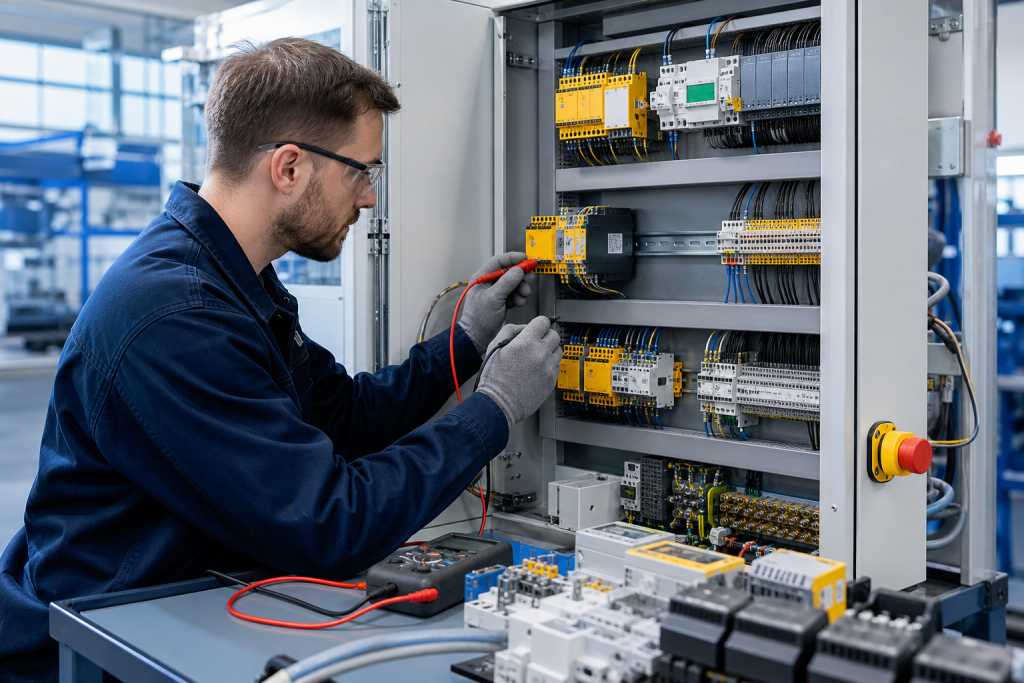
A safety relay, safety I/O module, or emergency-stop interface is not an ordinary control component. It participates in a defined safety function, so replacing it requires more than matching the housing or terminal count. The replacement must fit the circuit, the reset behavior, the monitoring arrangement, and the machine documentation.
For a reliable industrial safety module RFQ, begin with the installed function and exact model identity. Do not assume that a standard relay, a similar safety relay, or a newer module is automatically equivalent. Confirm the application, wiring, diagnostics, and required validation information before a replacement is considered.
1. Identify the safety function first
Record what the module monitors or controls. It may be connected to an emergency stop, guard switch, light curtain, two-hand control, enabling device, safe stop input, or another protective function. Note what the circuit is designed to do when a fault occurs and what must happen before the machine can restart.
Also document the equipment around the module: safety controller, standard PLC, contactors, drive, motor, field device, and operator interface. This system context helps separate a dedicated safety module from a visually similar standard interface relay. The KNMKS Relays & Interface category and ABB brand reference can help organize a model-based inquiry.
2. Capture the complete model and hardware set
Photograph the front and side labels, terminal markings, status indicators, mounting position, and nearby wiring. Record the full manufacturer reference, suffix, revision, input voltage, output type, and any part number on the socket or terminal base. Some safety assemblies include a dedicated base, removable terminal, expansion unit, or coding accessory that is easy to miss in a close-up photo.
Count the input and output channels and note whether the module uses dual-channel inputs, monitored outputs, feedback contacts, or an external reset circuit. Record the terminal numbering exactly as shown in the cabinet drawing. Never infer a safety pinout from a similar-looking product.
3. Verify input devices and reset behavior
Describe the input device connected to the module and how it is wired. A guard switch, emergency-stop button, and light curtain can have different contact arrangements and diagnostic expectations. Record whether the circuit uses one or two channels, cross-fault detection, short-circuit monitoring, or a test pulse.
Document manual reset, automatic reset, monitored reset, and restart interlock behavior. A replacement that changes reset logic can alter the machine sequence even when the safety contacts appear to operate normally. Include the reset button location, feedback contact path, and contactor monitoring details in the RFQ notes.
4. Check ratings and output architecture
Record supply voltage, input current, output contact arrangement, switching voltage, switching current, minimum load, and the type of device being disconnected. Contactors, valves, drives, and other inductive loads may require suppression or a specific output arrangement. Note whether outputs are relay contacts, semiconductor outputs, or safety-rated solid-state channels.
For safety I/O or networked safety devices, capture the controller family, fieldbus or safety protocol, node or address information, firmware requirements, and configuration software. The module’s role in the safety system is part of compatibility and should be reviewed with the machine risk assessment and engineering documentation.
5. Confirm diagnostic and fault handling details
Record the meaning of status LEDs, diagnostic contacts, fault codes, and reset requirements. Check whether the control system expects a feedback signal from contactors or a specific healthy-state indication. A change in diagnostics can affect troubleshooting and may create a nuisance stop if the PLC logic interprets the signal differently.
Schneider Electric’s TM3 safety documentation describes safety module characteristics, wiring diagrams, and installation details. Rockwell Automation documentation for isolated safety output modules also emphasizes the relationship between the module, terminal base, grounding, and firmware or software requirements. These manufacturer references are useful for terminology and verification, but the installed machine documentation remains the basis for the final model review.
See the Schneider Electric TM3 safety module guide and Rockwell Automation safety output module instructions for reference.
6. Review mechanical fit and cabinet conditions
Measure module width, mounting method, terminal access, adjacent clearance, wiring direction, and removal space. Check the DIN rail, terminal base, bridging links, end stops, labels, and any interlocking accessories. A replacement can match the electrical function and still require a different base or cabinet modification.
Record temperature, vibration, dust, humidity, and cabinet ventilation. Photograph the complete installation so the review includes cable routing and neighboring components. This is especially important when the safety circuit must be tested during a short maintenance window.
7. Prepare an RFQ that supports verification
- Complete manufacturer model, suffix, revision, and visible cross-reference.
- Clear photos of labels, terminals, socket or base, indicators, and cabinet wiring.
- Safety function, input device, channel arrangement, reset method, and feedback circuit.
- Supply, output, load, contact, diagnostic, protocol, firmware, and configuration details.
- Controller, contactors, drives, field devices, cabinet drawing, and machine application.
- Quantity, destination country, replacement or project use, and required timing.
If the model is unclear, send the nameplate and wiring photos instead of guessing from the color or shape. The KNMKS product directory can be used to provide the existing reference and related system context in the inquiry.
Final replacement gate
Before approving a safety module replacement, confirm the safety function, input and reset behavior, output architecture, diagnostics, and mechanical installation. Any change to a safety-related circuit should be reviewed and validated by the responsible machine safety engineer. If one point is uncertain, keep the request at model-review stage and provide the missing drawing or photo.
KNMKS supports model-based inquiries for safety modules, interface relays, terminal components, and industrial control equipment. Send the exact reference, cabinet photos, quantity, destination, and application notes for a compatibility-focused RFQ review.
Related Product Paths