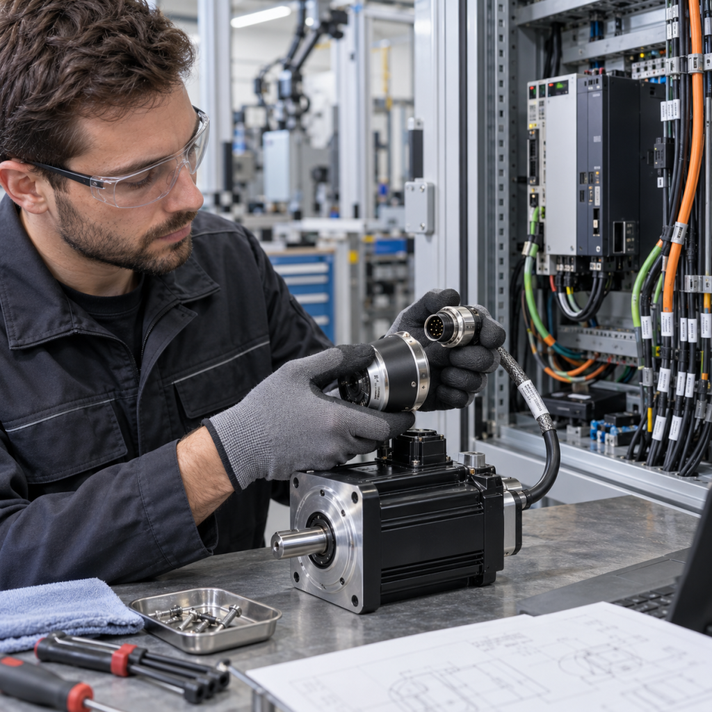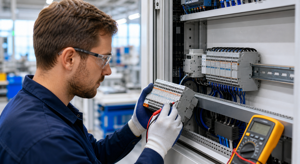
An encoder replacement can look straightforward when the part number is visible, but feedback devices are tightly connected to the motor, drive, controller, and mechanical installation. Encoder type, resolution, communication interface, mounting dimensions, and parameter data all affect whether the replacement can be commissioned correctly.
Before sending an industrial encoder replacement RFQ, document the installed motor and drive system as well as the encoder itself. A similar connector or matching shaft diameter is not enough to establish compatibility.
1. Identify the encoder’s role in the motion system
First determine whether the device provides motor feedback, load feedback, position feedback, speed feedback, commutation information, or a redundant measurement. Record the motor, servo drive, controller, and machine axis connected to it. Note whether the encoder is mounted on the motor shaft, gearbox, linear axis, or another mechanical point.
This system context matters because a motor-mounted encoder and a load-side encoder may use different scaling, feedback channels, and commissioning settings. The KNMKS Servo Systems category and Siemens brand reference can help organize the system information before the inquiry is sent.
2. Capture the complete identity and revision
Photograph the encoder label, connector, cable exit, mounting face, shaft or hollow-bore arrangement, and the motor nameplate. Record the complete manufacturer reference, suffix, revision, and any order code on the motor or drive documentation. Some encoder references differ by interface, resolution, temperature sensor, connector orientation, or factory-loaded motor data.
Do not crop out the motor label. The motor model can determine the correct encoder family, mounting kit, parameter set, and electrical interface. If more than one similar axis is installed, photograph each assembly separately to avoid mixing model references during an urgent maintenance request.
3. Verify feedback technology and interface
Record the feedback technology, including incremental A/B/Z signals, sine and cosine, resolver, SSI, EnDat, HIPERFACE, DRIVE-CLiQ, or another vendor-specific interface. Note whether the device is absolute or incremental and whether the drive expects serial identification or a manually entered parameter set.
Rockwell Automation documentation lists multiple feedback interface types, including digital quadrature, sine/cosine, SSI, resolver, EnDat, and vendor-specific serial interfaces. This is a useful reference for terminology, but the installed drive configuration and manufacturer documentation must determine the final match. See the Rockwell feedback interface documentation.
4. Check resolution, data format, and electrical details
Record pulses per revolution, counts per revolution, bit resolution, data length, output voltage, supply range, current draw, maximum speed, and signal frequency where applicable. Check whether the feedback cable includes separate power, signal pairs, shield, temperature sensor conductors, or a brake-related connection.
For serial encoders, document the communication format and any electronic nameplate or motor data stored in the device. For incremental encoders, record A, B, and index behavior, signal polarity, line-driver type, and termination expectations. A replacement that produces a signal but uses a different scaling or data format can make the axis position inaccurate.
5. Confirm mechanical mounting and alignment
Measure flange or mounting-hole dimensions, pilot diameter, shaft diameter, shaft length, keyway, hollow-bore size, clamping method, and connector orientation. Check the available clearance and whether the encoder uses a coupling, mounting arm, adapter plate, or special bracket.
Record the installation procedure and alignment references. Mechanical misalignment, excessive shaft load, incorrect coupling tension, or a damaged mounting surface can cause feedback faults even when the electrical model is correct. Include photos of the encoder mounted on the motor, not only a loose spare.
6. Review commissioning and replacement boundaries
Ask whether the drive requires encoder identification, motor parameter transfer, electronic nameplate reading, phasing, homing, or a new tuning procedure after replacement. Record the current fault code, drive firmware, controller software, and the last known working configuration if available.
Siemens service documentation for SIMOTICS encoder replacement states that the encoder type and replacement variant must be considered during the service process. It also describes checking motor operation before recommissioning. Use the Siemens SIMOTICS encoder replacement manual as a manufacturer reference, while following the exact procedure for the installed machine.
7. Prepare a complete encoder RFQ
- Complete encoder model, suffix, revision, and motor nameplate reference.
- Photos of the encoder label, connector, mounting face, shaft, and installed position.
- Feedback type, resolution, signal or serial interface, supply, and cable construction.
- Flange, shaft, bore, coupling, mounting dimensions, and connector orientation.
- Servo drive, controller, axis, firmware, fault code, and commissioning requirements.
- Quantity, destination country, replacement or project use, and required timing.
If the model is unclear, send the encoder and motor photos together with the drive model. The KNMKS product directory can be used to provide the existing reference and related motion-system context in the inquiry.
Final replacement gate
Before approving an encoder replacement, confirm the feedback role, interface, resolution, electrical requirements, mechanical mounting, and commissioning procedure as one system. A connector match or similar housing does not replace a documented compatibility check. If one point is uncertain, keep the request at model-review stage and provide the missing label or motor photo.
KNMKS supports model-based inquiries for encoders, servo components, feedback devices, and industrial control equipment. Send the exact references, installation photos, quantity, destination, and application notes for a compatibility-focused RFQ review.
Related Product Paths