
Overview
Siemens ULC0065 Migration-Ready Unitary Controller for Legacy BAS
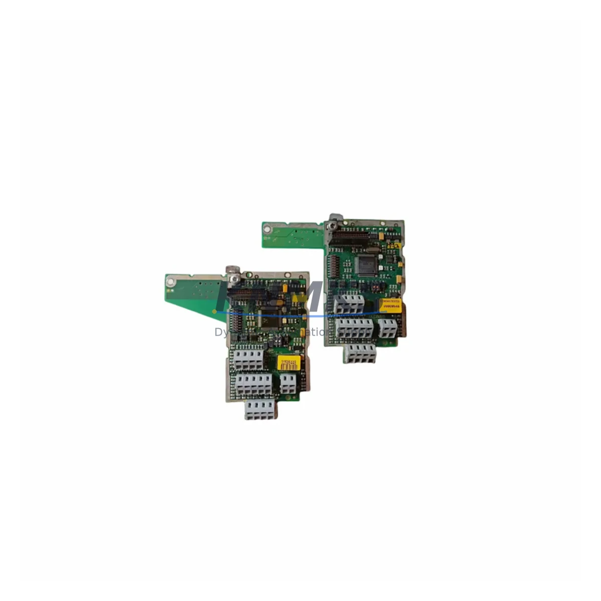
The Siemens ULC0065 is a migration-ready unitary controller engineered for facilities teams managing aging APOGEE building automation systems. As legacy Siemens field panels and unitary controllers reach end-of-life, the ULC0065 provides a validated replacement path that preserves existing BACnet/P1 bus topology, minimizes re-engineering effort, and eliminates the need for full system overhauls. Whether you are replacing a failed ULC0052, retiring an obsolete ULC0055, or consolidating control points across a multi-zone HVAC retrofit, the ULC0065 delivers the I/O capacity, communication compatibility, and firmware stability required for mission-critical building environments.
Facilities engineers and controls contractors frequently encounter the ULC0065 in projects involving air handling unit upgrades, VAV terminal unit replacements, and chiller plant modernization. Its compact DIN-rail form factor fits standard control cabinet enclosures without requiring panel modifications, and its terminal block layout is compatible with existing field wiring from predecessor models. Before installation, technicians should verify power supply capacity — the ULC0065 operates on 24 VAC and draws up to 15 VA — and confirm that the existing P1 bus segment can accommodate the additional node without exceeding the 32-device limit per trunk. Address assignment must be configured via onboard DIP switches prior to mounting, and the address map should be cross-referenced against the existing APOGEE Insight or APOGEE Automation Server database to prevent node conflicts.
Program migration from legacy ULC models requires exporting the existing control logic from the APOGEE Engineering Tool and validating point mapping against the ULC0065 I/O register set. Analog input scaling, binary output pulse widths, and PID loop parameters should be reviewed and adjusted where the hardware resolution differs from the predecessor unit. HMI graphic pages referencing the replaced controller’s device instance must be updated in the APOGEE Insight workstation to reflect the new device address and object identifiers. Communication link integrity should be verified using the P1 bus diagnostic utility before returning the system to automatic control.
In multi-controller retrofit projects, the ULC0065 is commonly deployed alongside the Siemens TEC (Terminal Equipment Controller) series for zone-level control, the Siemens RXC room controller for fan coil and heat pump applications, and the Siemens PXC Modular field panel as the supervisory BACnet/IP gateway. Power distribution within the control cabinet typically involves a Siemens SITOP PSU100S 24 VDC power supply for auxiliary circuits, while field device wiring may include Siemens ASC1 actuators and Siemens QAM room temperature sensors already present in the existing installation. Retaining these peripheral components during the ULC0065 swap reduces material cost and shortens commissioning time significantly.
Migration Compatibility Table
| Parameter | Legacy ULC0052 / ULC0055 | Siemens ULC0065 | Migration Note |
|---|---|---|---|
| Power Supply | 24 VAC, Class 2 | 24 VAC, Class 2, 15 VA max | Verify transformer VA capacity before swap |
| Communication Bus | BACnet/P1 (RS-485) | BACnet/P1 (RS-485) | Direct bus compatibility; re-address via DIP switch |
| Analog Inputs | 4 UI (universal) | 6 UI (universal) | Additional I/O available; update point database |
| Binary Outputs | 4 BO (relay) | 6 BO (relay) | Verify relay contact ratings match load |
| Analog Outputs | 2 AO (0–10 VDC) | 2 AO (0–10 VDC) | Direct replacement; no scaling change required |
| Terminal Block | Screw-type, 3.5 mm pitch | Screw-type, 3.5 mm pitch | Existing field wiring reusable |
| Mounting | DIN rail / panel mount | DIN rail / panel mount | No panel modification required |
| Firmware Compatibility | APOGEE FW 2.x / 3.x | APOGEE FW 3.x and above | Confirm Insight server version supports ULC0065 |
| Programming Tool | APOGEE Engineering Tool | APOGEE Engineering Tool | Export/import logic; validate point mapping |
| Support terms | End-of-life / no support | support terms confirmed by quotation | Pre-shipment tested; in-stock for immediate dispatch |
Retrofit Planning for Existing Automation Systems
A successful ULC0065 retrofit begins with a thorough audit of the existing control cabinet. Technicians should document the current P1 bus segment layout, record all device addresses in use, and photograph terminal block wiring before disconnecting any field devices. The ULC0065 occupies the same DIN-rail slot width as the ULC0052 and ULC0055, so panel space is rarely a constraint; however, clearance for the RJ-11 P1 bus connector and the 24 VAC power terminals should be confirmed against the enclosure depth.
Where the retrofit scope extends beyond a single controller replacement, the project typically involves coordinating the ULC0065 with adjacent system components. The Siemens PXC Compact field panel, if present as the BACnet/IP router for the P1 trunk, must have its routing table updated to recognize the new device instance assigned to the ULC0065. In VAV applications, Siemens TEC terminal equipment controllers on the same P1 segment continue to operate without interruption during the ULC0065 swap, provided bus termination resistors remain correctly positioned at the segment endpoints. For chiller plant or AHU applications where the ULC0065 interfaces with a Siemens RWD or RLU universal controller via hardwired analog signals, input/output scaling should be verified at the receiving controller after the replacement is complete.
Wiring adaptation is straightforward in most cases: the ULC0065 uses the same 3.5 mm pitch screw terminal layout as its predecessors, and existing 18 AWG shielded cable runs are fully compatible. Shield grounding should be maintained at one end only to prevent ground loops. If the existing installation includes a Siemens OCI600 or OCI700 communication interface for legacy P2 bus devices, the ULC0065 does not natively support P2; a protocol gateway or a separate P2-capable controller must be retained for those endpoints.
Downtime Control During System Migration
Minimizing downtime during a ULC0065 replacement requires pre-staging the new controller with the correct device address, verified firmware version, and a pre-loaded control program before the maintenance window begins. The APOGEE Engineering Tool allows offline program compilation and download preparation, so the replacement unit arrives on-site ready for a rapid swap. Field technicians should schedule the cutover during low-occupancy periods and coordinate with the building management team to place affected zones in manual override or local thermostat control for the duration of the swap.
The physical replacement sequence — power down, disconnect field wiring, remove legacy unit, mount ULC0065, reconnect terminals, restore power, verify P1 bus communication, and confirm point values in APOGEE Insight — typically takes 45 to 90 minutes per controller when pre-staging is complete. HMI graphic pages should be validated immediately after the controller comes online to confirm that all analog values are within expected ranges and that binary output states match the commanded positions. Any discrepancies in PID loop behavior should be addressed during the commissioning window before the zone is returned to automatic control.
For multi-controller projects where several ULC units are being replaced in sequence, a phased approach — replacing one controller per maintenance window — allows the building automation system to remain operational throughout the retrofit and reduces the risk of widespread control disruption. Pre-shipment testing of each ULC0065 unit, combined with the support terms confirmed by quotation coverage, ensures that field failures during the retrofit window are addressed without additional procurement delays.
Retrofit Support FAQ
Q: Is the ULC0065 a direct drop-in replacement for the ULC0052 and ULC0055?
A: Yes, in most installations. The ULC0065 shares the same BACnet/P1 bus protocol, 24 VAC power requirement, DIN-rail mounting format, and 3.5 mm screw terminal layout. The primary differences are the expanded I/O count and updated firmware baseline. Point database entries for the replaced unit must be updated in the APOGEE Engineering Tool, and the device address must be reassigned via DIP switch to match the legacy unit’s address or a newly allocated address in the segment map.
Q: What commissioning steps are required after installing the ULC0065?
A: After mounting and wiring, confirm P1 bus communication from the APOGEE Insight workstation or field panel. Download the pre-compiled control program, verify all analog input readings against field sensor values, exercise each binary output manually to confirm relay operation, and validate PID loop setpoints. Update HMI graphic pages to reflect the new device instance if the address has changed. Document the commissioning results and retain a copy of the final program download for the project record.
Q: Does each ULC0065 unit undergo pre-shipment testing?
A: Yes. Every ULC0065 unit is functionally tested prior to dispatch, covering power-up behavior, I/O point verification, and P1 bus communication handshake. Units are shipped with a support terms confirmed by quotation from the date of delivery. In-stock units are available for same-day or next-business-day dispatch to support emergency replacement scenarios.
Q: What is the support terms and return policy for the ULC0065?
A: The ULC0065 carries a support terms confirmed by quotation covering manufacturing defects and functional failures under normal operating conditions. Units that fail within the confirmed support period are replaced or repaired at no additional cost. Contact the sales team with the unit serial number and a description of the fault to initiate a support terms claim. Stock availability is maintained to support rapid support terms replacements without extended lead times.
© 2026 KNMKS. All rights reserved.
Original Source: https://knmks.com
Contact: admin@knmks.com | +86 18359268345
Product Identification
- Brand / Ecosystem
-
Siemens
Siemens - Model / Series
- ULC0065
- Product Family
- PLCs & Controllers
- Availability Status
- Available on request after model and quantity confirmation
- Inquiry Type
- B2B RFQ, replacement inquiry and project spare-part request
- Pre-Quote Check
- Exact SKU, brand, series, quantity, nameplate photos and destination country are checked before quotation
System Path
Where this product fits in the KNMKS automation structure.
Specification & Inquiry Focus
- Control platform
- PLC, PAC and modular controllers
- Common needs
- CPU, rack, power and I/O expansion
- Project support
- Replacement, cabinet build and maintenance
Buyer Confirmation
Information KNMKS checks before replying.
- Exact model
- ULC0065
- Brand / ecosystem
- Siemens
- Product family
- PLCs & Controllers
- Application note
- Replacement, maintenance, project build or spare-part list
- Useful photos
- Nameplate, installed unit, cabinet layout or connector side
- Delivery details
- Quantity, destination country and target schedule
Document Support
Files and notes can be confirmed during quotation.
- Product photos or nameplate confirmation when available
- Packing and delivery notes before quotation confirmation
- Support scope and delivery terms confirmed per inquiry
- Export document coordination for qualified B2B requests
Inquiry Support
- Model cross-checking before quotation
- CPU, power, rack and expansion module matching
- Support for replacement and project inquiry
What to Send Us
- Brand and exact model number: Siemens ULC0065
- Quantity and required delivery time
- Application, replacement requirement or nameplate photo
- Destination country and shipping preference
RFQ Preparation
This is a product inquiry page built for RFQ communication.
Fast Model Check
Send this model to KNMKS for confirmation.
Include quantity, destination country and photos if this is a maintenance replacement. The inquiry will be saved with a reference number after submission.
Brand & Compatibility Note
KNMKS displays automation product information for well-known industrial brand ecosystems and compatible replacement references. Brand names are used for product identification and compatibility reference only; final availability and commercial terms are confirmed per quotation.
 Manufacturing
 Machine Tools
 Packaging
 Energy & Power
 HMI & Displays
 Servo Systems
 Variable Frequency Drives
 Sensors