
Overview
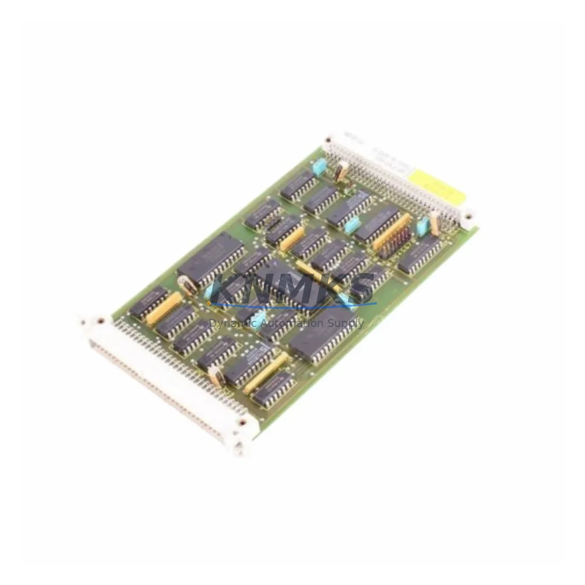
Siemens C8451-A1-A197 Maintenance-Proven Spare Part for Factory Uptime
The Siemens C8451-A1-A197 is a CPU module designed for the SICOMP SMP series — a ruggedized programmable controller platform widely deployed in process automation, machine control, and industrial production environments. For maintenance engineers managing aging control systems, this module represents a critical spare: one that directly determines whether a production line resumes within hours or remains offline for days pending procurement.
Sourced as an original Siemens component, the C8451-A1-A197 is verified for compatibility with SICOMP SMP backplane configurations. Each unit undergoes functional inspection and power-on testing prior to shipment, ensuring that the module you receive is ready for immediate installation. With a support terms confirmed by quotation and long-term supply commitment, this spare is suited for both emergency replacement and planned inventory stocking.
Industrial buyers and MRO procurement teams managing Siemens SICOMP-based systems will find this module essential for sustaining system continuity, particularly in facilities where legacy automation infrastructure must remain operational beyond the original product lifecycle.
Spare Maintenance Table
| SKU / Part Number | C8451-A1-A197 |
| Brand | Siemens |
| Series | SICOMP SMP |
| Module Type | CPU Module |
| Product Category | Electrical Equipment & Supplies > Industrial Automation > PLC Modules |
| Origin | Germany |
| Compatibility | SICOMP SMP backplane systems; verify rack slot and firmware revision before installation |
| Supply Voltage | Per SICOMP SMP system bus specification (confirm with rack power supply rating) |
| Weight | 300 g (approx.) |
| Application Environment | Industrial control cabinets, process automation panels, machine control enclosures |
| Installation | Backplane slot insertion; observe ESD precautions; confirm address and DIP switch settings |
| Maintenance Recommendation | Inspect battery backup, I/O bus connectors, and communication interfaces at each scheduled maintenance interval |
| Support terms | 12 Months from date of shipment |
| Pre-shipment Testing | Power-on functional verification performed on every unit |
Maintenance Planning for Continuous Operation
Replacing the C8451-A1-A197 CPU module is rarely an isolated task. In a SICOMP SMP control cabinet, the CPU interfaces directly with the backplane bus, power supply rails, I/O modules, and communication interfaces. A thorough maintenance plan should address each of these subsystems in parallel to avoid repeat downtime.
Begin with the rack power supply module — confirm that output voltage is within specification before inserting a new CPU. A marginal power supply is a common root cause of CPU failures and will damage a replacement module if left unchecked. Next, inspect the backplane bus connector for oxidation, bent pins, or mechanical damage. Poor backplane contact causes intermittent faults that are difficult to diagnose after the fact.
Review the digital and analog I/O modules installed in adjacent slots. If the CPU failure was preceded by I/O errors or signal anomalies, those modules should be tested independently. Similarly, check any communication modules — such as PROFIBUS DP or serial interface cards — for firmware compatibility with the replacement CPU revision. A mismatch in firmware or hardware revision can prevent the system from initializing correctly.
For systems with HMI panels connected via serial or fieldbus, verify that the communication parameters (baud rate, station address, protocol) are correctly configured after CPU replacement. HMI connection loss is a frequent post-replacement issue that delays system restart unnecessarily.
Inspect terminal blocks and field wiring at the I/O marshalling area. Loose terminals and degraded insulation are common in older installations and should be addressed during any planned CPU replacement. Also check signal isolators on analog input channels — these components age independently of the PLC and can introduce measurement errors that appear as CPU or software faults.
Finally, verify the condition of fuses and circuit protection on the 24 VDC control power rail. A blown fuse on the CPU supply circuit is sometimes the actual cause of a CPU fault indication, and replacing the module without addressing the fuse will result in immediate repeat failure.
Stocking the C8451-A1-A197 alongside complementary spares — including a backup power supply module, one or two I/O modules, and a communication interface card — provides a complete emergency kit for the SICOMP SMP system and minimizes mean time to repair across all foreseeable fault scenarios.
Site Replacement Workflow
1. Pre-replacement preparation: Download and archive the current CPU program and configuration data before removing the module. Confirm that a valid backup exists on an external storage device or engineering workstation. Note all DIP switch settings, address configurations, and firmware version labels on the existing module.
2. Power isolation: De-energize the control cabinet following site lockout/tagout procedures. Discharge any residual voltage on the backplane power rails before handling the CPU module. Use ESD wrist strap and mat throughout the replacement procedure.
3. Module removal and inspection: Remove the C8451-A1-A197 from its backplane slot. Inspect the slot connector and surrounding modules for signs of heat damage, contamination, or mechanical stress. Clean the slot with dry compressed air if necessary.
4. Replacement module configuration: Set DIP switches and address jumpers on the new C8451-A1-A197 to match the original configuration. Verify hardware revision compatibility with the installed backplane and adjacent modules.
5. Reinstallation and power-on: Seat the module firmly into the backplane slot. Restore control power and observe the CPU status LEDs during initialization. A normal startup sequence indicates successful hardware installation.
6. Program restore and verification: Download the archived program to the CPU. Perform I/O force tests on critical channels to confirm correct signal routing. Verify HMI communication and fieldbus node status before returning the system to automatic operation.
7. Documentation: Record the replacement date, new module serial number, and any configuration changes in the site maintenance log. Update the spare parts inventory to reflect the consumed unit and initiate a reorder to maintain minimum stock levels.
Spare Parts Support FAQ
Q1: Is the C8451-A1-A197 compatible with all SICOMP SMP rack configurations?
The C8451-A1-A197 is designed for the SICOMP SMP series, but compatibility depends on the specific rack generation, backplane revision, and firmware version in your installation. Before ordering, provide your existing module’s hardware revision and the rack model number for confirmation. Our technical team can assist with compatibility verification prior to shipment.
Q2: What does the support terms confirmed by quotation cover?
The support terms confirmed by quotation cover manufacturing defects and functional failures under normal operating conditions from the date of shipment. Each unit is power-on tested before dispatch. Support requests are supported with replacement or refund, subject to inspection of the returned unit. Physical damage caused by incorrect installation, overvoltage, or ESD is excluded.
Q3: Can you supply the C8451-A1-A197 on an ongoing basis for long-term inventory programs?
Yes. We maintain sourcing relationships that support repeat and scheduled procurement for MRO and spare parts programs. For facilities managing multiple SICOMP SMP systems or planning multi-year maintenance contracts, we recommend establishing a blanket order or minimum stock agreement to ensure availability and price stability.
Q4: What information should I provide to confirm the correct spare part before purchase?
Please provide the full part number (C8451-A1-A197), the hardware revision marked on your existing module, the SICOMP SMP rack model, and the application context (process control, machine automation, etc.). This allows us to confirm the correct variant, check stock, and advise on any known compatibility considerations before the order is placed.
© 2026 KNMKS. All rights reserved.
Original Source: https://knmks.com
Contact: admin@knmks.com | +86 18359268345
Product Identification
- Brand / Ecosystem
-
Siemens
Siemens - Model / Series
- C8451-A1-A197
- Product Family
- PLCs & Controllers
- Availability Status
- Available on request after model and quantity confirmation
- Inquiry Type
- B2B RFQ, replacement inquiry and project spare-part request
- Pre-Quote Check
- Exact SKU, brand, series, quantity, nameplate photos and destination country are checked before quotation
System Path
Where this product fits in the KNMKS automation structure.
Specification & Inquiry Focus
- Control platform
- PLC, PAC and modular controllers
- Common needs
- CPU, rack, power and I/O expansion
- Project support
- Replacement, cabinet build and maintenance
Buyer Confirmation
Information KNMKS checks before replying.
- Exact model
- C8451-A1-A197
- Brand / ecosystem
- Siemens
- Product family
- PLCs & Controllers
- Application note
- Replacement, maintenance, project build or spare-part list
- Useful photos
- Nameplate, installed unit, cabinet layout or connector side
- Delivery details
- Quantity, destination country and target schedule
Document Support
Files and notes can be confirmed during quotation.
- Product photos or nameplate confirmation when available
- Packing and delivery notes before quotation confirmation
- Support scope and delivery terms confirmed per inquiry
- Export document coordination for qualified B2B requests
Inquiry Support
- Model cross-checking before quotation
- CPU, power, rack and expansion module matching
- Support for replacement and project inquiry
What to Send Us
- Brand and exact model number: Siemens C8451-A1-A197
- Quantity and required delivery time
- Application, replacement requirement or nameplate photo
- Destination country and shipping preference
RFQ Preparation
This is a product inquiry page built for RFQ communication.
Fast Model Check
Send this model to KNMKS for confirmation.
Include quantity, destination country and photos if this is a maintenance replacement. The inquiry will be saved with a reference number after submission.
Brand & Compatibility Note
KNMKS displays automation product information for well-known industrial brand ecosystems and compatible replacement references. Brand names are used for product identification and compatibility reference only; final availability and commercial terms are confirmed per quotation.
 Manufacturing
 Machine Tools
 Packaging
 Energy & Power
 HMI & Displays
 Servo Systems
 Variable Frequency Drives
 Sensors