
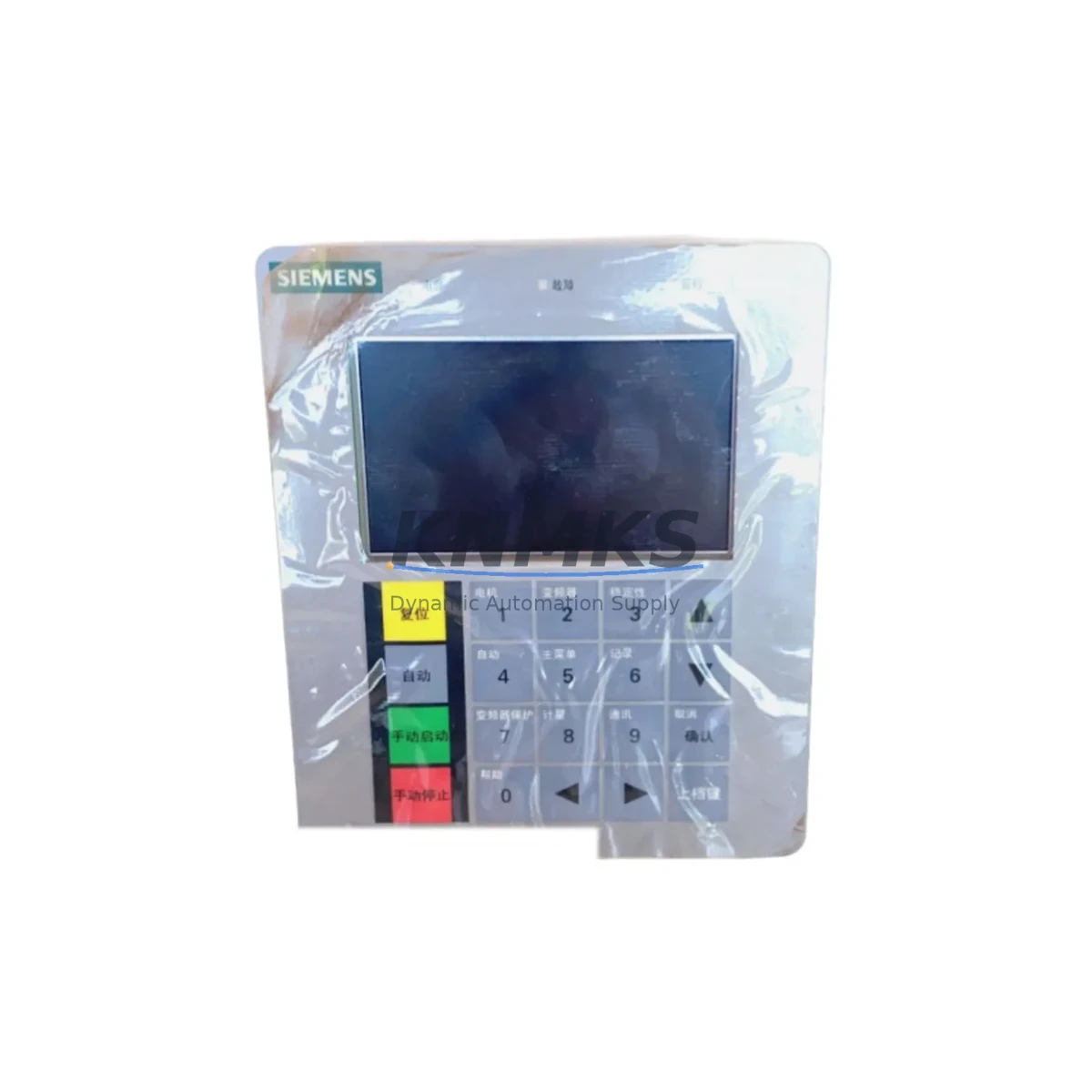
Overview
Siemens A5E02624585 Migration-Ready Interface Module: Legacy System Retrofit & Compatibility Upgrade
The Siemens A5E02624585 is a migration-ready interface module engineered for SIMATIC S7 control platforms, purpose-built to address the growing demand for discontinued spare part replacement, legacy control cabinet upgrades, and I/O system modernization. As Siemens progressively phases out older S7-300 and S7-400 series components, the A5E02624585 serves as a verified drop-in replacement that preserves existing program logic, terminal wiring layouts, and backplane communication integrity — dramatically reducing retrofit risk and unplanned downtime on the production floor.
Engineers and maintenance teams undertaking control system migrations frequently encounter the challenge of sourcing interface modules that maintain backward compatibility with legacy racks, power supplies, and communication buses. The A5E02624585 addresses this directly: it is dimensionally compatible with standard S7 rack slots, supports the established backplane interface protocol, and requires no firmware re-flashing in most direct-replacement scenarios. Before installation, technicians should verify the rack’s power budget — particularly when the existing power supply module (such as a PS 307 or PS 405 series unit) is already operating near capacity — to ensure the A5E02624585’s current draw remains within the available headroom.
Terminal wiring compatibility is a critical checkpoint during any interface module swap. The A5E02624585 retains the standard 40-pin front connector pinout common across the SIMATIC S7-300 I/O family, meaning existing field wiring harnesses can typically be reconnected without modification. However, technicians should cross-reference the original wiring diagram against the module’s channel assignment table, especially in installations where signal isolators or marshalling panels have been inserted between the field device and the PLC rack. Where CP 343-1 or CP 443-1 communication processors are present in the same rack, module address assignments must be re-confirmed in STEP 7 or TIA Portal after the swap to prevent address conflicts that could disrupt PROFIBUS DP or Industrial Ethernet communication links.
For facilities running mixed-generation control architectures — for example, a legacy S7-300 rack interfacing with a newer S7-1500 controller via PN/DP coupler — the A5E02624585 supports seamless integration without requiring HMI screen redesign. Existing WinCC or SIMATIC HMI panel configurations referencing the module’s data blocks will continue to function correctly, provided the DB structure and tag addresses are preserved during the program migration. This is particularly valuable in retrofit projects where minimizing HMI rework is a key cost-control objective.
Installation space confirmation is straightforward: the A5E02624585 occupies a single slot on a standard S7-300 DIN rail-mounted rack (such as the UR1 or UR2 universal rack) and does not require adjacent slot clearance beyond standard module spacing. In cramped control cabinets where space is at a premium, this single-slot footprint simplifies the physical retrofit without requiring panel re-layout. When replacing modules in an ET 200M distributed I/O station, the same slot-compatibility rules apply, and the IM 153-x interface module governing that station should be checked for firmware version compatibility to ensure the A5E02624585 is correctly enumerated on the PROFIBUS segment.
Pre-shipment testing is conducted on every A5E02624585 unit: each module undergoes functional verification including backplane communication handshake testing, channel integrity checks, and power-on self-test validation before dispatch. Units are supplied with a support terms confirmed by quotation covering manufacturing defects and functional failures under normal operating conditions. Global stock is maintained to support urgent breakdown replacement scenarios, with expedited shipping available to minimize production line downtime.
Migration Compatibility Table
| Parameter | Details |
|---|---|
| Compatible Platform | SIMATIC S7-300, ET 200M Distributed I/O |
| Rack Compatibility | UR1, UR2 Universal Racks; standard DIN rail mounting |
| Slot Footprint | Single slot; no adjacent clearance required |
| Front Connector | Standard 40-pin S7-300 front connector (field wiring reusable) |
| Backplane Interface | S7-300 backplane bus; compatible with standard rack communication protocol |
| Communication Compatibility | PROFIBUS DP, MPI; Industrial Ethernet via CP modules in same rack |
| Power Supply Compatibility | PS 307 / PS 405 series; verify available power budget before installation |
| Programming Environment | STEP 7 v5.x, TIA Portal (with legacy S7-300 support enabled) |
| Firmware Update Required | Not required in most direct-replacement scenarios |
| HMI Compatibility | WinCC, SIMATIC HMI panels; existing DB/tag structure preserved |
| Replacement Recommendation | Direct drop-in for discontinued A5E02624585 units; verify module address in STEP 7 |
| Commissioning Note | Re-confirm module address assignments after swap; test PROFIBUS segment integrity |
| Pre-Shipment Testing | Functional verification, backplane handshake, channel integrity, POST |
| Support terms | support terms confirmed by quotation — manufacturing defects and functional failures |
Retrofit Planning for Existing Automation Systems
A successful retrofit begins well before the module arrives on site. The first step is a full audit of the existing control cabinet: document the rack layout, record the slot positions of all installed modules, and photograph the existing wiring before any disassembly. In a typical S7-300 installation, the rack may contain a mix of digital input modules (SM 321 series), digital output modules (SM 322 series), analog input/output modules (SM 331/332/334), and communication processors — all of which must remain undisturbed during the A5E02624585 swap.
Power budget verification is non-negotiable. Sum the current consumption of all modules in the rack (available from each module’s datasheet) and confirm the installed PS 307 5A or PS 307 10A power supply module has sufficient reserve capacity to support the A5E02624585 without triggering an overload condition. If the power supply is already at or near its rated output, a power supply upgrade should be planned as part of the retrofit scope.
For systems using a CP 343-1 Lean or CP 343-1 Advanced communication processor for Industrial Ethernet connectivity, the module address table in STEP 7 must be updated after the A5E02624585 is installed. Failure to do so can result in the CPU reporting a configuration mismatch fault, which will prevent the program from transitioning to RUN mode. Similarly, in installations where an IM 360/361 interface module pair is used to extend the rack across multiple tiers, the interface module addressing must be re-validated post-swap.
Where signal isolators (such as PHOENIX CONTACT or Pepperl+Fuchs barrier modules) are installed between field instruments and the PLC I/O, technicians should verify that the isolator output signal range remains within the A5E02624585’s input specification. This is particularly relevant in analog channel applications where 4–20 mA loop integrity must be maintained throughout the retrofit. Programming cables (PC Adapter USB or MPI/PROFIBUS adapter) should be on hand during commissioning to allow real-time online monitoring of the module’s diagnostic buffer in STEP 7 or TIA Portal.
Downtime Control During System Migration
Minimizing production downtime during a control system retrofit requires a structured, pre-planned approach. The most effective strategy is to prepare a complete replacement kit — including the A5E02624585, a pre-configured front connector with wiring labels, and a backup copy of the current PLC program — before scheduling the maintenance window. This eliminates the risk of discovering missing components or configuration gaps during the live swap.
Where the process allows, a cold-swap procedure is preferred: power down the rack in a controlled sequence (CPU to STOP, then power supply off), remove the existing module, install the A5E02624585, reconnect the front connector, and restore power. The CPU should be held in STOP mode while the module is enumerated and the hardware configuration is downloaded from STEP 7 or TIA Portal. Only after the diagnostic buffer confirms no configuration faults should the CPU be transitioned to RUN mode.
For critical processes where even brief interruptions are unacceptable, consider staging the retrofit during a planned production changeover or scheduled preventive maintenance window. Pre-testing the A5E02624585 on a bench rack with a representative program segment before the live installation further reduces commissioning time on the production floor. Retaining the original module as a tested spare — rather than discarding it — provides an immediate fallback option if unexpected compatibility issues arise during the initial post-swap production run.
All field wiring reconnections should be torque-verified to the terminal manufacturer’s specification, and a full I/O force test should be performed before releasing the system to production. Document the completed retrofit in the equipment maintenance log, including the module serial number, installation date, and commissioning technician’s name, to support future maintenance planning and support terms claim processing.
Retrofit Support FAQ
Q: Is the Siemens A5E02624585 a direct replacement for the original discontinued module?
A: Yes. The A5E02624585 is a verified drop-in replacement for the original Siemens part of the same SKU. It maintains dimensional, electrical, and backplane interface compatibility with standard S7-300 racks. No hardware modification is required in the majority of direct-replacement applications. Customers are advised to confirm the module address assignment in STEP 7 or TIA Portal after installation.
Q: What commissioning steps are required after installing the A5E02624585?
A: After physical installation and front connector reconnection, download the existing hardware configuration from STEP 7 or TIA Portal to the CPU. Monitor the diagnostic buffer for any configuration mismatch or module fault messages. Re-confirm module address assignments, verify PROFIBUS DP segment integrity if applicable, and perform a full I/O force test before transitioning the CPU to RUN mode. Commissioning typically takes 30–90 minutes for a direct replacement in a well-documented installation.
Q: Has the A5E02624585 been tested before shipment, and what support terms is provided?
A: Every unit undergoes pre-shipment functional verification including backplane communication handshake testing, channel integrity checks, and power-on self-test validation. All units are supplied with a support terms confirmed by quotation covering manufacturing defects and functional failures under normal operating conditions. Support requests are supported by our technical team at admin@knmks.com.
Q: Is stock available for urgent breakdown replacement orders?
A: Yes. Global inventory is maintained specifically to support urgent breakdown and emergency replacement scenarios. Expedited shipping options are available to minimize production line downtime. Contact our team at admin@knmks.com or +86 18359268345 to confirm current stock availability and lead times for your region.
© 2026 KNMKS. All rights reserved.
Original Source: https://knmks.com
Contact: admin@knmks.com | +86 18359268345
Product Identification
- Brand / Ecosystem
-
Siemens
Siemens - Model / Series
- A5E02624585
- Product Family
- PLCs & Controllers
- Availability Status
- Available on request after model and quantity confirmation
- Inquiry Type
- B2B RFQ, replacement inquiry and project spare-part request
- Pre-Quote Check
- Exact SKU, brand, series, quantity, nameplate photos and destination country are checked before quotation
System Path
Where this product fits in the KNMKS automation structure.
Specification & Inquiry Focus
- Control platform
- PLC, PAC and modular controllers
- Common needs
- CPU, rack, power and I/O expansion
- Project support
- Replacement, cabinet build and maintenance
Buyer Confirmation
Information KNMKS checks before replying.
- Exact model
- A5E02624585
- Brand / ecosystem
- Siemens
- Product family
- PLCs & Controllers
- Application note
- Replacement, maintenance, project build or spare-part list
- Useful photos
- Nameplate, installed unit, cabinet layout or connector side
- Delivery details
- Quantity, destination country and target schedule
Document Support
Files and notes can be confirmed during quotation.
- Product photos or nameplate confirmation when available
- Packing and delivery notes before quotation confirmation
- Support scope and delivery terms confirmed per inquiry
- Export document coordination for qualified B2B requests
Inquiry Support
- Model cross-checking before quotation
- CPU, power, rack and expansion module matching
- Support for replacement and project inquiry
What to Send Us
- Brand and exact model number: Siemens A5E02624585
- Quantity and required delivery time
- Application, replacement requirement or nameplate photo
- Destination country and shipping preference
RFQ Preparation
This is a product inquiry page built for RFQ communication.
Fast Model Check
Send this model to KNMKS for confirmation.
Include quantity, destination country and photos if this is a maintenance replacement. The inquiry will be saved with a reference number after submission.
Brand & Compatibility Note
KNMKS displays automation product information for well-known industrial brand ecosystems and compatible replacement references. Brand names are used for product identification and compatibility reference only; final availability and commercial terms are confirmed per quotation.
 Manufacturing
 Machine Tools
 Packaging
 Energy & Power
 HMI & Displays
 Servo Systems
 Variable Frequency Drives
 Sensors