
Overview
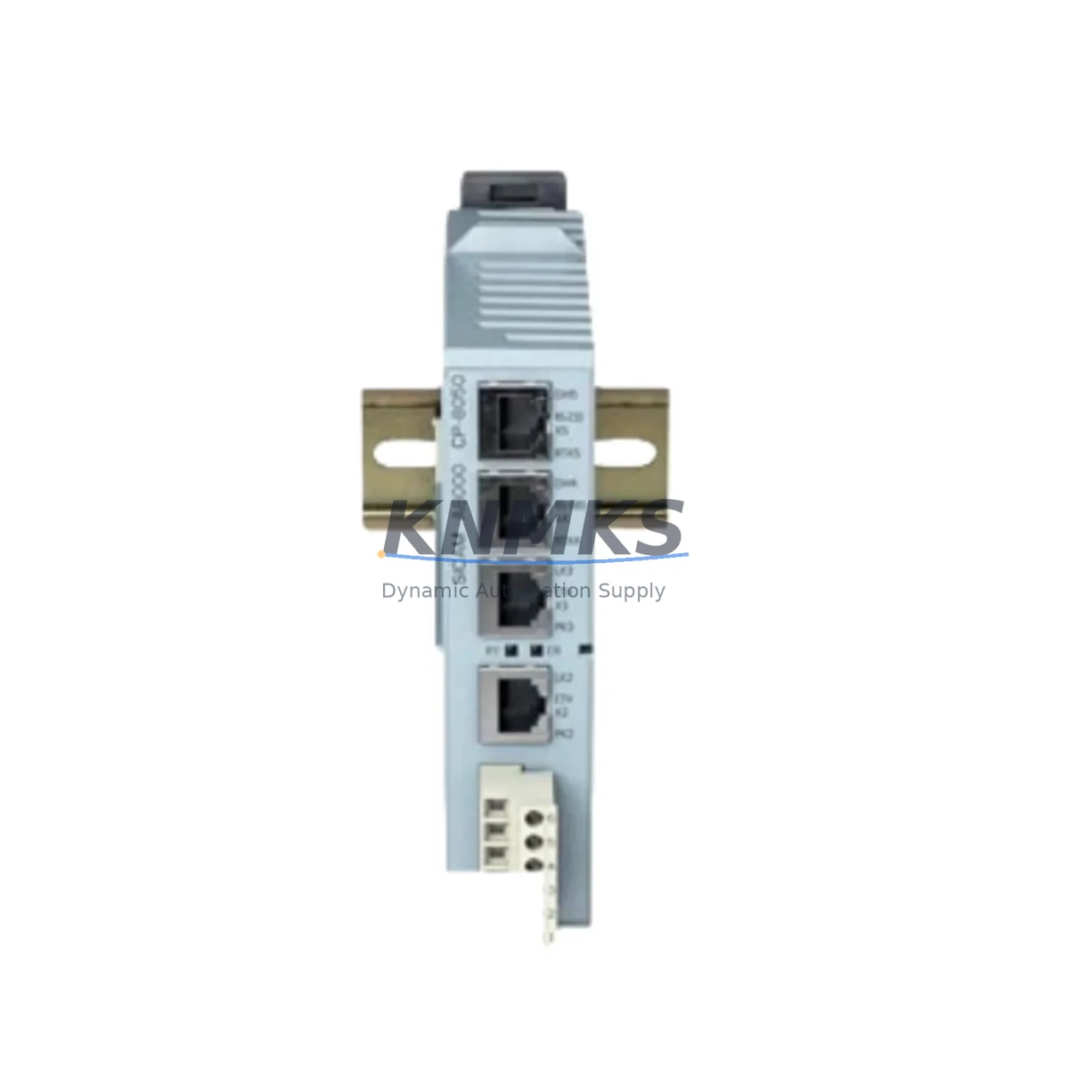
Siemens 6MF28050AA00 Migration-Ready Master Module: Legacy System Migration and Compatible Upgrade
The Siemens 6MF28050AA00 is a SIMATIC NET Master Module engineered for seamless integration into existing Siemens automation architectures. As industrial facilities face increasing pressure to modernize aging control infrastructure, the 6MF28050AA00 serves as a critical bridge between legacy field bus networks and contemporary control platforms. Whether you are replacing a discontinued module in a PROFIBUS-based production line, upgrading a control cabinet originally commissioned in the early 2000s, or extending the operational life of a SIMATIC S5 or early S7-300 installation, this module provides the communication backbone required to maintain system continuity without a full platform overhaul.
Engineers undertaking retrofit projects must carefully evaluate several parameters before committing to a replacement module. Power supply capacity within the existing rack is a primary concern — the 6MF28050AA00 draws from the backplane bus, and the installed power supply module, such as a PS 307 or PS 305, must have sufficient headroom to support the additional load. Terminal wiring compatibility should be verified against the original field wiring documentation, particularly for RS-485 PROFIBUS segments where bus termination resistors and cable shielding practices directly affect signal integrity. Backplane interface alignment with the existing rack — whether a UR1, UR2, or CR2 chassis — must be confirmed to ensure physical and electrical compatibility.
Module addressing is another area requiring careful attention during migration. In multi-master PROFIBUS networks, the 6MF28050AA00’s station address must be configured to avoid conflicts with existing DP masters and slave devices. Program compatibility should be assessed at the function block level: existing OB, FB, and FC structures referencing the original communication module’s data areas may require adaptation in STEP 7 or TIA Portal to correctly map to the replacement module’s I/O image. HMI screen configurations in WinCC or TP/OP panels that display communication status or diagnostic information linked to the original module address will also need to be updated to reflect the new module’s data structure.
Communication link verification is essential before returning the system to production. PROFIBUS segment topology, including repeater placement and cable length calculations, should be reviewed to confirm that the replacement module operates within the network’s timing budget. Installation space within the control cabinet must accommodate the module’s physical dimensions, and DIN rail or rack mounting clearances should be checked against the existing enclosure layout. Firmware version compatibility between the 6MF28050AA00 and the CPU module — such as a CPU 315-2 DP or CPU 317-2 PN/DP — should be confirmed using the Siemens compatibility matrix prior to commissioning.
Migration Compatibility Table
| Parameter | Details |
|---|---|
| SKU / Part Number | 6MF28050AA00 |
| Brand / Series | Siemens SIMATIC NET |
| Module Type | PROFIBUS DP Master Communication Module |
| Interface / Backplane | Compatible with UR1, UR2, CR2 racks; S7-300 backplane bus |
| Communication Protocol | PROFIBUS DP (RS-485); compatible with existing DP master/slave topologies |
| Installation Requirements | Standard DIN rail or rack slot mounting; verify slot position and power budget |
| Replacement Compatibility | Suitable for replacing discontinued SIMATIC NET master modules in legacy S7-300/S5 migration projects |
| Firmware Compatibility | Verify against CPU firmware version using Siemens compatibility matrix |
| Commissioning Notes | Reconfigure station address; update STEP 7 / TIA Portal program references; verify HMI data links |
| Origin | Germany (DE) |
| Support terms | support terms confirmed by quotation — covers manufacturing defects and functional failures under normal operating conditions |
Retrofit Planning for Existing Automation Systems
A successful retrofit begins with a thorough audit of the existing control architecture. In a typical S7-300 installation, the 6MF28050AA00 occupies a rack slot alongside modules such as the CPU 315-2 DP, analog input modules like the SM 331, digital output modules such as the SM 322, and a PS 307 power supply. Before removing the legacy master module, engineers should document all PROFIBUS slave addresses, GSD file assignments, and diagnostic buffer entries to preserve the network configuration baseline.
In projects involving I/O expansion as part of the upgrade, ET 200M distributed I/O stations connected via PROFIBUS DP may need to be reconfigured in HW Config to reflect the new master module’s slot assignment. Where the retrofit also involves a transition from PROFIBUS to PROFINET, an IE/PB Link PN IO gateway can be used to bridge the existing PROFIBUS segment to the new PROFINET backbone, allowing the 6MF28050AA00 to continue serving legacy field devices while the upper-level network is modernized. Programming cables such as the PC Adapter USB A2 are required for online diagnostics and firmware updates during the commissioning phase.
Control cabinet upgrades that incorporate the 6MF28050AA00 should also account for signal isolation requirements. Where analog signals from legacy sensors are routed through the cabinet, signal isolators or barriers may be required to prevent ground loops that could affect communication reliability. Backplane current consumption should be recalculated after adding the replacement module to ensure the installed power supply module remains within its rated output capacity.
Downtime Control During System Migration
Minimizing production downtime during a module replacement requires a structured approach to pre-commissioning preparation. Before the scheduled maintenance window, engineers should export the complete STEP 7 or TIA Portal project, including all hardware configuration data, symbol tables, and program blocks, to a secure backup location. A full CPU memory backup using a SIMATIC Memory Card ensures that the original program logic can be restored rapidly in the event of an unexpected issue during the swap.
During the physical replacement, the PROFIBUS network should be taken offline in a controlled sequence, starting from the outermost slave devices and working inward toward the master. This approach prevents uncontrolled fault propagation across the network and allows each segment to be isolated and verified independently. After installing the 6MF28050AA00, the module should be powered up in offline mode before reconnecting the PROFIBUS cable, allowing initial diagnostics to confirm that the module is recognized correctly by the CPU before network traffic is restored.
Field control continuity can be maintained during the migration window by placing affected process loops in manual mode at the DCS or SCADA level, ensuring that actuators hold their last commanded position while the communication link is re-established. Once the 6MF28050AA00 is online and all slave devices are communicating correctly, process loops can be returned to automatic control in a staged sequence, with each loop verified against its setpoint before the next is released. This approach limits exposure to simultaneous process disturbances and reduces the risk of safety system activation during the transition.
Retrofit Support FAQ
Q: Is the 6MF28050AA00 a direct drop-in replacement for the discontinued SIMATIC NET master module in my S7-300 rack?
A: In most S7-300 rack configurations, the 6MF28050AA00 is compatible as a functional replacement. Physical slot dimensions and backplane connector pinout are consistent with the S7-300 rack standard. However, the station address and GSD file assignments must be reconfigured in STEP 7 or TIA Portal to match the original network topology. We recommend verifying the hardware configuration against your existing project before installation.
Q: What commissioning steps are required after installing the 6MF28050AA00?
A: After physical installation, connect the programming cable and open the hardware configuration in STEP 7 or TIA Portal. Assign the correct PROFIBUS station address, download the updated hardware configuration to the CPU, and perform a network scan to confirm that all slave devices are recognized. Check the diagnostic buffer for any communication faults and verify that all I/O data is correctly mapped before returning the system to automatic operation.
Q: How do I verify wiring compatibility between the 6MF28050AA00 and my existing PROFIBUS cable installation?
A: The 6MF28050AA00 uses a standard 9-pin Sub-D PROFIBUS connector. Verify that the existing cable uses the correct PROFIBUS cable type (Type A recommended for most installations), that bus termination is active only at the two physical ends of the segment, and that cable shielding is grounded at one point per segment to prevent ground loops. A PROFIBUS tester can be used to verify signal quality before and after the module replacement.
Q: What does the support terms confirmed by quotation cover, and how is inventory availability managed?
A: The support terms confirmed by quotation cover manufacturing defects and functional failures under normal industrial operating conditions. Each unit undergoes functional testing prior to shipment to verify communication performance and module initialization. We maintain dedicated inventory for SIMATIC NET components to support urgent replacement requirements, and most orders are processed for same-day or next-business-day dispatch. Contact our team for current stock levels and lead time confirmation for your specific project schedule.
© 2026 KNMKS. All rights reserved.
Original Source: https://knmks.com
Contact: admin@knmks.com | +86 18359268345
Product Identification
- Brand / Ecosystem
-
Siemens
Siemens - Model / Series
- 6MF28050AA00
- Product Family
- PLCs & Controllers
- Availability Status
- Available on request after model and quantity confirmation
- Inquiry Type
- B2B RFQ, replacement inquiry and project spare-part request
- Pre-Quote Check
- Exact SKU, brand, series, quantity, nameplate photos and destination country are checked before quotation
System Path
Where this product fits in the KNMKS automation structure.
Specification & Inquiry Focus
- Control platform
- PLC, PAC and modular controllers
- Common needs
- CPU, rack, power and I/O expansion
- Project support
- Replacement, cabinet build and maintenance
Buyer Confirmation
Information KNMKS checks before replying.
- Exact model
- 6MF28050AA00
- Brand / ecosystem
- Siemens
- Product family
- PLCs & Controllers
- Application note
- Replacement, maintenance, project build or spare-part list
- Useful photos
- Nameplate, installed unit, cabinet layout or connector side
- Delivery details
- Quantity, destination country and target schedule
Document Support
Files and notes can be confirmed during quotation.
- Product photos or nameplate confirmation when available
- Packing and delivery notes before quotation confirmation
- Support scope and delivery terms confirmed per inquiry
- Export document coordination for qualified B2B requests
Inquiry Support
- Model cross-checking before quotation
- CPU, power, rack and expansion module matching
- Support for replacement and project inquiry
What to Send Us
- Brand and exact model number: Siemens 6MF28050AA00
- Quantity and required delivery time
- Application, replacement requirement or nameplate photo
- Destination country and shipping preference
RFQ Preparation
This is a product inquiry page built for RFQ communication.
Fast Model Check
Send this model to KNMKS for confirmation.
Include quantity, destination country and photos if this is a maintenance replacement. The inquiry will be saved with a reference number after submission.
Brand & Compatibility Note
KNMKS displays automation product information for well-known industrial brand ecosystems and compatible replacement references. Brand names are used for product identification and compatibility reference only; final availability and commercial terms are confirmed per quotation.
 Manufacturing
 Machine Tools
 Packaging
 Energy & Power
 HMI & Displays
 Servo Systems
 Variable Frequency Drives
 Sensors