
Overview
Siemens 16267-1-2 Migration-Ready Interface for MODULNET MNI Legacy Control Systems
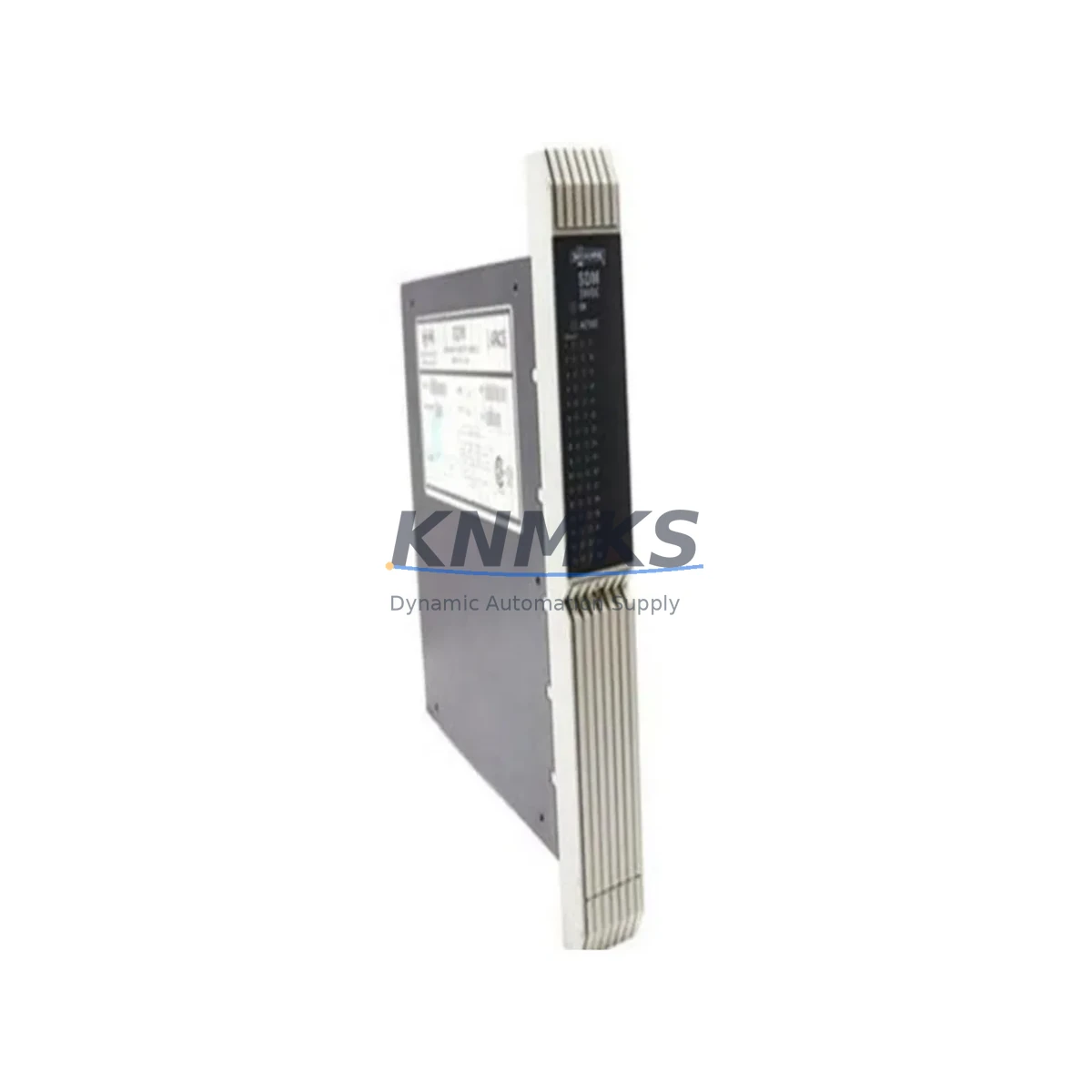
The Siemens 16267-1-2 is an ISA Bus interface module designed for the MODULNET MNI (Modular Network Interface) communication platform, widely deployed in legacy distributed control systems across process industries, power generation, and discrete manufacturing. As original equipment manufacturers phase out support for first-generation MODULNET architectures, the 16267-1-2 has become a critical spare and migration component for engineers tasked with extending the operational life of existing control cabinets or executing phased system upgrades without full platform replacement.
This module provides the physical and logical bridge between ISA-bus backplane infrastructure and the MODULNET communication layer, enabling continued data exchange between field I/O, operator stations, and supervisory controllers. For facilities running legacy Siemens S5-series controllers or early SIMATIC configurations, the 16267-1-2 is frequently the last serviceable interface before a full migration to S7-300, S7-400, or S7-1500 architecture becomes unavoidable. Sourcing a verified, tested unit directly reduces unplanned downtime and defers capital expenditure on full system replacement.
Before installing a replacement 16267-1-2, engineers must confirm several critical parameters. Power supply capacity on the existing backplane must support the module’s ISA bus draw; older MODULNET racks may require a supplementary Siemens 6ES5 955-series power supply module if the original PSU is degraded or undersized. Terminal wiring should be verified against the original I/O assignment sheets — particularly for analog signal channels where shielding continuity and ground reference points affect measurement accuracy. Backplane slot addressing must match the original hardware configuration stored in the CPU’s system data block; incorrect slot assignment will cause the CPU to fault on startup.
Program compatibility is a frequent concern during MODULNET interface replacement. If the host controller is a Siemens S5-115U or S5-135U CPU, the existing STEP 5 program must be backed up before any hardware swap. The organization blocks (OBs) and function blocks (FBs) referencing the MNI interface must be reviewed to confirm that the replacement module’s firmware revision is compatible with the existing DB structures. In cases where the original module carried a firmware version below 3.x, a firmware update may be required before the replacement unit will initialize correctly on the bus.
For facilities also upgrading their HMI layer — for example, migrating from legacy WinCC 6.x panels to current SIMATIC HMI TP or KP series — the 16267-1-2 replacement is often performed in parallel with reconfiguring the communication link between the MNI network and the HMI station. This requires verifying that the MPI or PROFIBUS DP communication module on the HMI side is correctly parameterized to the updated network node address of the replacement interface. Where PROFIBUS DP is the upstream protocol, a Siemens CP 342-5 or CP 343-5 communications processor may be present in the same rack and must be checked for address conflicts after the 16267-1-2 is installed.
Physical installation space should be confirmed before ordering. The 16267-1-2 occupies a standard ISA-format slot in the MODULNET rack. If the original rack has been partially populated with newer modules during incremental upgrades, slot spacing and guide-rail alignment must be verified. In some retrofit scenarios, the existing MODULNET rack or backplane assembly itself requires replacement due to corrosion, connector wear, or mechanical damage — in which case the 16267-1-2 is installed into a new rack alongside other retained modules such as digital input/output modules and analog signal conditioning cards from the same generation.
Commissioning after replacement follows a structured sequence: power-off installation, visual inspection of connector pins, power-on with CPU in STOP mode, hardware configuration download, transition to RUN mode, and verification of all I/O process images against the original baseline. Field debug tools such as a Siemens PC Adapter USB or MPI programming cable connected to a STEP 5 or STEP 7 workstation are required for online diagnostics. All units supplied by KNMKS are pre-tested under load conditions prior to dispatch, with a support terms confirmed by quotation covering manufacturing defects and functional failure under normal operating conditions.
Migration Compatibility Table
| Parameter | Specification / Recommendation |
|---|---|
| Module Type | ISA Bus Interface Module for MODULNET MNI |
| Compatible Host Controllers | Siemens S5-115U, S5-135U, S5-155U; early SIMATIC S7 with MNI gateway |
| Backplane Interface | ISA Bus (16-bit); standard MODULNET rack slot |
| Communication Protocol | MODULNET MNI proprietary; MPI/PROFIBUS DP upstream (configuration-dependent) |
| Power Requirement | Confirm backplane PSU capacity before installation; supplement with 6ES5 955-series if required |
| Slot Addressing | Must match original hardware configuration in CPU system data block |
| Firmware Compatibility | Verify firmware revision ≥ 3.x for full STEP 5 DB compatibility |
| Programming Tool Required | STEP 5 v7.x or STEP 7 v5.x with MPI/PC Adapter USB cable |
| HMI Reconfiguration | Required if HMI communication node address changes post-replacement |
| Installation Space | Standard ISA-format MODULNET rack slot; verify guide-rail alignment |
| Pre-shipment Testing | Full functional test under load conditions at KNMKS facility |
| Support terms | 12 months from date of dispatch; covers manufacturing defects and functional failure |
Retrofit Planning for Existing Automation Systems
A successful retrofit begins with a complete audit of the existing control cabinet. For systems built around the MODULNET MNI architecture, this typically means documenting every module in the rack — including the Siemens 6ES5 095-series central controller, any installed 6ES5 300-series digital I/O modules, 6ES5 460-series analog input modules, and the existing power supply. Each module’s firmware version, slot address, and wiring termination must be recorded before any hardware is disturbed.
Where the retrofit scope extends beyond a single interface module replacement, engineers frequently encounter the need to upgrade the MODULNET rack backplane itself, particularly in installations over 15 years old where connector oxidation has caused intermittent communication faults. In parallel, the MPI or PROFIBUS DP segment connecting the MODULNET network to upstream SCADA or DCS layers should be tested for signal integrity — degraded cable shielding or incorrect termination resistors are common causes of post-retrofit communication instability.
For facilities planning a phased migration toward S7-300 or S7-1500 architecture, the 16267-1-2 serves as a bridge component that allows the legacy MODULNET I/O layer to remain operational while the CPU and communication infrastructure is progressively modernized. During this transition period, a Siemens IM 360/361 interface module pair may be used to extend the S7-300 rack across multiple rows, accommodating both legacy and new I/O modules in the same physical cabinet. Signal isolators and terminal adapters are often required at the field wiring interface to reconcile differences in signal levels and grounding schemes between old and new module generations.
Downtime Control During System Migration
Minimizing production downtime during a MODULNET interface replacement requires preparation that begins well before the maintenance window. The existing STEP 5 or STEP 7 program — including all data blocks, organization blocks, and hardware configuration files — must be archived to an offline backup before any hardware is touched. Where possible, a simulation or offline test environment should be used to verify that the replacement module’s configuration produces the expected I/O process image before the live system is modified.
During the physical swap, the sequence of operations matters: remove the failed or end-of-life 16267-1-2 only after confirming the CPU is in STOP mode and the backplane power is isolated. Install the replacement unit, verify connector seating, restore power, and download the hardware configuration before transitioning the CPU to RUN. This sequence protects the original program logic from corruption and prevents uncontrolled output states during the transition.
For critical processes where even a brief interruption is unacceptable, a hot-standby or redundant controller configuration should be considered as part of the broader migration plan. In non-redundant systems, coordinating the replacement during a scheduled maintenance shutdown — and pre-staging all required components including the 16267-1-2, programming cable, and a laptop with the correct STEP 5 software version — reduces the risk of extended downtime caused by missing tools or incompatible software at the time of the repair.
Retrofit Support FAQ
Q: Is the Siemens 16267-1-2 a direct drop-in replacement for the original MODULNET MNI interface?
A: In most configurations, yes. The 16267-1-2 is designed for the MODULNET MNI platform and occupies a standard ISA-format rack slot. However, firmware revision compatibility with the host CPU’s system data block must be verified before installation. KNMKS can advise on firmware requirements based on your CPU model and STEP 5 program version.
Q: What wiring changes are required when replacing the 16267-1-2?
A: In a like-for-like replacement, no field wiring changes should be necessary. Terminal assignments on the MODULNET rack are fixed by the backplane design. However, if the replacement is being performed as part of a broader cabinet upgrade, terminal block labeling should be verified against the original I/O list, and shield grounding continuity should be checked at both the module and field device ends.
Q: How do I verify the replacement module is functioning correctly after installation?
A: Connect a programming device running STEP 5 or STEP 7 via MPI/PC Adapter USB cable. Go online with the CPU, navigate to the hardware diagnostics view, and confirm that the 16267-1-2 is recognized at the correct rack slot with no fault indicators. Verify that the I/O process image for all channels associated with the MNI interface matches expected field values. KNMKS provides a pre-shipment test report for each unit on request.
Q: What does the support terms confirmed by quotation cover, and what is the supply lead time?
A: The support terms confirmed by quotation cover manufacturing defects and functional failure under normal industrial operating conditions from the date of dispatch. It does not cover damage caused by incorrect installation, overvoltage, or environmental factors outside the module’s rated specifications. Stock availability is confirmed at time of order; most units ship within 3–5 business days. Express dispatch options are available for urgent maintenance requirements.
© 2026 KNMKS. All rights reserved.
Original Source: https://knmks.com
Contact: admin@knmks.com | +86 18359268345
Product Identification
- Brand / Ecosystem
-
SIEMENS
Siemens - Model / Series
- 16267-1-2
- Product Family
- PLCs & Controllers
- Availability Status
- Available on request after model and quantity confirmation
- Inquiry Type
- B2B RFQ, replacement inquiry and project spare-part request
- Pre-Quote Check
- Exact SKU, brand, series, quantity, nameplate photos and destination country are checked before quotation
System Path
Where this product fits in the KNMKS automation structure.
Specification & Inquiry Focus
- Control platform
- PLC, PAC and modular controllers
- Common needs
- CPU, rack, power and I/O expansion
- Project support
- Replacement, cabinet build and maintenance
Buyer Confirmation
Information KNMKS checks before replying.
- Exact model
- 16267-1-2
- Brand / ecosystem
- SIEMENS
- Product family
- PLCs & Controllers
- Application note
- Replacement, maintenance, project build or spare-part list
- Useful photos
- Nameplate, installed unit, cabinet layout or connector side
- Delivery details
- Quantity, destination country and target schedule
Document Support
Files and notes can be confirmed during quotation.
- Product photos or nameplate confirmation when available
- Packing and delivery notes before quotation confirmation
- Support scope and delivery terms confirmed per inquiry
- Export document coordination for qualified B2B requests
Inquiry Support
- Model cross-checking before quotation
- CPU, power, rack and expansion module matching
- Support for replacement and project inquiry
What to Send Us
- Brand and exact model number: SIEMENS 16267-1-2
- Quantity and required delivery time
- Application, replacement requirement or nameplate photo
- Destination country and shipping preference
RFQ Preparation
This is a product inquiry page built for RFQ communication.
Fast Model Check
Send this model to KNMKS for confirmation.
Include quantity, destination country and photos if this is a maintenance replacement. The inquiry will be saved with a reference number after submission.
Brand & Compatibility Note
KNMKS displays automation product information for well-known industrial brand ecosystems and compatible replacement references. Brand names are used for product identification and compatibility reference only; final availability and commercial terms are confirmed per quotation.
 Manufacturing
 Machine Tools
 Packaging
 Energy & Power
 HMI & Displays
 Servo Systems
 Variable Frequency Drives
 Sensors