
Overview
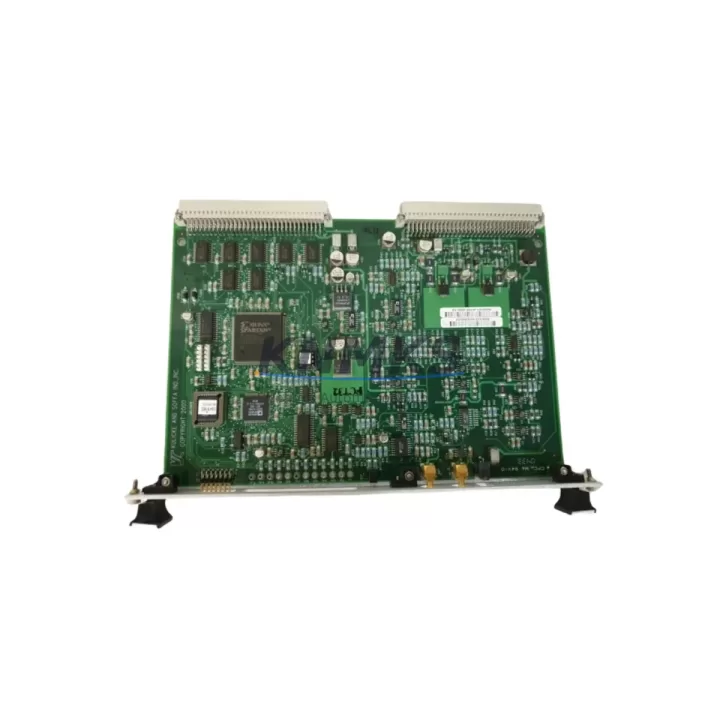
Kulicke & Soffa 8001-4186 Migration-Ready PCB Control Board: Legacy Wire Bonder System Upgrade
The Kulicke & Soffa 8001-4186 is a migration-ready PCB control board engineered as a direct replacement for legacy K&S wire bonder platforms. As semiconductor packaging lines age and OEM support for discontinued control hardware becomes increasingly scarce, the 8001-4186 provides a verified, drop-in compatible solution that restores full machine functionality without requiring a complete system overhaul. Whether you are managing a production floor running K&S 8000-series wire bonders or maintaining a mixed-generation bonding cell, this board is designed to minimize retrofit complexity and protect your existing capital investment.
Procurement teams and process engineers working with legacy wire bonder infrastructure frequently encounter the challenge of sourcing discontinued PCB assemblies. The 8001-4186 addresses this directly: it is stocked, tested, and shipped with a support terms confirmed by quotation, giving maintenance teams a reliable path to system recovery without extended lead times or costly machine replacement. Each unit undergoes functional verification prior to dispatch, covering power rail integrity, signal output continuity, and interface compatibility with the K&S bonding head control architecture.
When planning a retrofit around the 8001-4186, engineers should confirm several critical parameters before installation. Power supply compatibility is the first checkpoint — the board operates within the voltage and current envelope of the original K&S control cabinet, but aging power supply modules such as the K&S 8001-3200 series PSU should be load-tested to confirm they can sustain stable output under the restored control board’s demand. Terminal wiring from the motion control harness must be verified against the original schematic; connector pinouts on the 8001-4186 are preserved from the legacy design, but wire insulation degradation on older machines can introduce intermittent faults that appear as board-level failures.
Backplane interface alignment is another area requiring careful attention. The 8001-4186 seats into the K&S main chassis backplane, and the edge connector must be fully seated without mechanical stress. If the chassis has been subject to thermal cycling over many years of operation, backplane socket wear can cause marginal contact resistance — a condition that should be inspected and cleaned before the replacement board is installed. Module addressing, where applicable to the control architecture, should be confirmed against the machine’s configuration record to ensure the replacement board is recognized correctly by the system controller.
Program logic compatibility is a key concern for any PCB-level replacement in a wire bonder environment. The 8001-4186 is designed to operate with the existing bonding program library stored in the machine controller — no reprogramming of bond parameters, loop profiles, or force settings is required in a standard swap scenario. However, if the machine has been running a customized firmware version, the firmware revision on the replacement board should be confirmed against the installed version. In cases where the HMI display panel — such as the K&S operator interface terminal — shows unexpected alarm states after board installation, a firmware synchronization step may be required before production can resume.
Communication link integrity between the 8001-4186 and upstream process control systems should be validated as part of commissioning. Wire bonder cells integrated into automated material handling environments may rely on RS-232, GPIB, or proprietary serial protocols for lot tracking and recipe download. These communication paths should be tested end-to-end after board replacement to confirm that the bonding cell responds correctly to host commands and that production data logging resumes without gaps. Where the wire bonder interfaces with a vision alignment system or a wafer handling module, the handshake timing between the control board and peripheral subsystems should be verified under a controlled test cycle before returning the machine to full production.
Installation space within the K&S control cabinet is a practical consideration that is sometimes overlooked in retrofit planning. The 8001-4186 matches the original board’s form factor, but technicians should confirm that adjacent modules — including I/O expansion boards, signal conditioning cards, and any field-installed interface adapters — have not been repositioned in ways that would obstruct proper seating or airflow around the replacement board. Adequate cooling is essential for long-term reliability in a production environment where the control cabinet may be subject to elevated ambient temperatures.
Migration Compatibility Table
| Parameter | Details |
|---|---|
| Replacement Target | Kulicke & Soffa 8001-4186 (original OEM part) |
| Compatible Platform | K&S 8000-series wire bonder control systems |
| Interface / Connector | Backplane edge connector — matches original chassis pinout |
| Installation Requirement | Direct board swap; no chassis modification required |
| Communication Compatibility | RS-232 / GPIB / proprietary serial (platform-dependent) |
| Firmware | Confirm revision matches installed machine firmware version |
| Commissioning | Power rail test, terminal inspection, comms link validation, test bond cycle |
| Support terms | 12 months from date of shipment |
Retrofit Planning for Existing Automation Systems
A successful 8001-4186 retrofit begins with a structured assessment of the surrounding control architecture. The K&S wire bonder platform is typically integrated with a range of supporting hardware that must remain functional through the board replacement process. The main power supply module feeding the control board should be tested under load before the new board is installed — an aging PSU that delivers marginal voltage can cause the replacement board to exhibit erratic behavior that is incorrectly attributed to the board itself. Similarly, the I/O expansion modules connected to the control board’s peripheral bus should be inspected for connector wear and signal integrity before the retrofit proceeds.
The bonding head motion control subsystem, which communicates with the 8001-4186 through dedicated signal lines, should be verified to be operating within specification. Encoder feedback signals, limit switch inputs, and force sensor outputs all interface with the control board and must be confirmed as clean and within tolerance before the replacement board is powered up. If the machine includes a vision alignment system with its own dedicated processing board, the interface between the vision subsystem and the main control board should be tested as part of the commissioning sequence.
For facilities managing multiple K&S wire bonder units, a standardized retrofit checklist covering the power supply module, backplane connector condition, I/O expansion board status, communication interface cables, HMI operator terminal firmware, and signal isolation components will significantly reduce per-machine retrofit time and ensure consistent outcomes across the production floor. Maintaining a documented configuration record for each machine — including the firmware version, module addresses, and communication settings — is essential for efficient future maintenance and spare parts planning.
Downtime Control During System Migration
Minimizing unplanned downtime during a PCB control board replacement requires preparation that begins before the machine is taken offline. The replacement 8001-4186 should be on-site and verified before the original board is removed. A pre-swap checklist should capture the current machine configuration, including any operator-adjusted bond parameters, alarm history, and communication settings, so that these can be confirmed as restored after the new board is installed.
The original board should be removed carefully, with all connector positions documented photographically before disconnection. The replacement board should be installed in a powered-down cabinet, with all connectors re-seated and verified before power is applied. Initial power-up should be performed with the bonding head in a safe home position, and the first operational check should be a controlled test bond cycle on a non-production substrate to confirm that bond force, loop height, and placement accuracy are within specification before production resumes.
For facilities where wire bonder downtime has a direct impact on die attach or packaging line throughput, maintaining a stocked spare of the 8001-4186 as a critical spare part is a practical risk mitigation strategy. With a support terms confirmed by quotation and verified pre-shipment testing, the replacement board can be held in controlled storage and deployed immediately when needed, reducing mean time to repair to the duration of the physical swap and commissioning sequence rather than the lead time for sourcing a replacement part under emergency conditions.
Retrofit Support FAQ
Q: Is the 8001-4186 a direct drop-in replacement for the original K&S part?
A: Yes. The 8001-4186 is designed as a direct replacement for the original OEM board, matching the backplane connector pinout, form factor, and electrical interface of the legacy part. No chassis modification is required for a standard installation.
Q: What commissioning steps are required after installation?
A: After physical installation, the recommended commissioning sequence includes a power rail verification, terminal wiring inspection, communication link test, firmware revision confirmation, and a controlled test bond cycle before returning the machine to production. This sequence typically requires two to four hours for an experienced technician.
Q: How is the board tested before shipment?
A: Each 8001-4186 unit undergoes functional testing prior to dispatch, covering power supply rail integrity, signal output verification, and interface continuity. A test report is available upon request. The board is shipped with a support terms confirmed by quotation covering manufacturing defects and functional failures under normal operating conditions.
Q: What is the stock availability and lead time?
A: The 8001-4186 is maintained availability confirmed by RFQ for immediate dispatch. Standard shipping lead time is three to seven business days depending on destination. For urgent requirements, expedited shipping options are available. Contact our sales team to confirm current stock levels and delivery schedule for your location.
© 2026 KNMKS. All rights reserved.
Original Source: https://knmks.com
Contact: admin@knmks.com | +86 18359268345
Product Identification
- Brand / Ecosystem
-
Other Brands
Assorted Brands - Model / Series
-
8001-4186
Assorted Series - Product Family
- Other Components
- Availability Status
- Available on request after model and quantity confirmation
- Inquiry Type
- B2B RFQ, replacement inquiry and project spare-part request
- Pre-Quote Check
- Exact SKU, brand, series, quantity, nameplate photos and destination country are checked before quotation
System Path
Where this product fits in the KNMKS automation structure.
Specification & Inquiry Focus
- Component range
- Breakers, terminals and cabinet accessories
- Common needs
- Model, photo and installation requirement
- Project support
- Maintenance and mixed spare-part inquiry
Buyer Confirmation
Information KNMKS checks before replying.
- Exact model
- 8001-4186
- Brand / ecosystem
- Other Brands
- Product family
- Other Components
- Application note
- Replacement, maintenance, project build or spare-part list
- Useful photos
- Nameplate, installed unit, cabinet layout or connector side
- Delivery details
- Quantity, destination country and target schedule
Document Support
Files and notes can be confirmed during quotation.
- Product photos or nameplate confirmation when available
- Packing and delivery notes before quotation confirmation
- Support scope and delivery terms confirmed per inquiry
- Export document coordination for qualified B2B requests
Inquiry Support
- Mixed automation spare parts inquiry
- Cabinet component and accessory support
- Model identification from photos or labels
What to Send Us
- Brand and exact model number: Other Brands 8001-4186
- Quantity and required delivery time
- Application, replacement requirement or nameplate photo
- Destination country and shipping preference
RFQ Preparation
This is a product inquiry page built for RFQ communication.
Fast Model Check
Send this model to KNMKS for confirmation.
Include quantity, destination country and photos if this is a maintenance replacement. The inquiry will be saved with a reference number after submission.
Brand & Compatibility Note
KNMKS displays automation product information for well-known industrial brand ecosystems and compatible replacement references. Brand names are used for product identification and compatibility reference only; final availability and commercial terms are confirmed per quotation.
 Manufacturing
 Machine Tools
 Packaging
 Energy & Power
 PLCs & Controllers
 HMI & Displays
 Servo Systems
 Variable Frequency Drives