
Overview
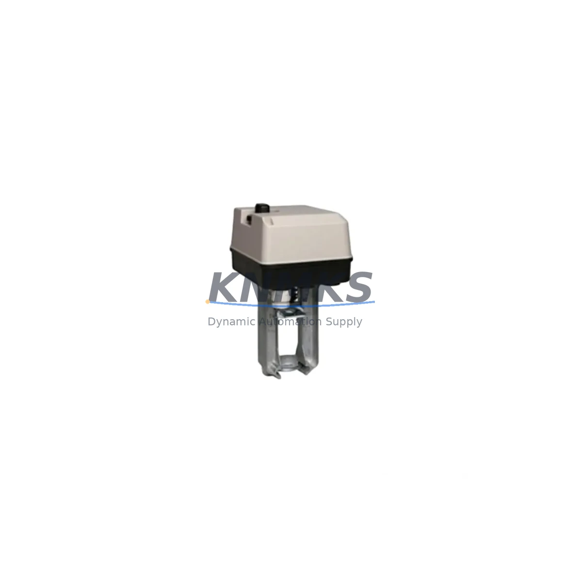
Honeywell ML6420A3015 Migration-Ready Linear Actuator for Legacy Control Systems
The Honeywell ML6420A3015 is a spring-return linear valve actuator engineered for direct drop-in replacement of legacy ML6420 Series actuators in aging HVAC and building automation control systems. As facilities managers and controls engineers face increasing pressure to modernize obsolete valve control infrastructure without full system overhauls, the ML6420A3015 provides a validated migration path that preserves existing wiring, valve body interfaces, and control signal architecture. Operating at 230VAC with a 500N rated force output and a standard 20mm stroke, this actuator is fully compatible with Honeywell’s Spyder and Excel series controllers, as well as third-party DDC platforms that output a standard 0–10V or on/off control signal.
When replacing an end-of-life ML6420A1015 or ML6420A2015 in a chilled water or heating hot water valve application, engineers must verify the existing terminal block wiring against the ML6420A3015 terminal layout. The actuator uses a three-wire connection (L, N, and signal), and in most legacy installations the signal wire is already configured for 0–10V modulating control, which the ML6420A3015 accepts natively. Spring-return direction (fail-open or fail-closed) should be confirmed against the original valve body specification before installation, as reversing the spring-return direction requires a physical actuator swap rather than a software parameter change.
For panel integrators upgrading control cabinets that house Honeywell Excel 10 or Excel 50 controllers, the ML6420A3015 can be driven directly from the AO (analog output) channels without additional signal conditioning. Where legacy systems use a Honeywell W7750 or W7752 zone controller, the actuator’s input impedance is compatible with the controller’s output drive capability, eliminating the need for a signal isolator or booster relay. In installations where the original actuator was wired through a Honeywell Q7055 or Q7056 switching relay module for on/off control, the ML6420A3015 can be configured for two-position operation by connecting only the L and N terminals and using the internal spring return for the de-energized position.
Migration Compatibility Table
| Parameter | Legacy ML6420A1015 / A2015 | ML6420A3015 (This Unit) | Migration Note |
|---|---|---|---|
| Supply Voltage | 230VAC 50/60Hz | 230VAC 50/60Hz | Direct replacement — no transformer change required |
| Control Signal | 0–10V / On-Off | 0–10V / On-Off | Compatible with existing DDC AO wiring |
| Stroke | 20mm | 20mm | No valve body modification required |
| Rated Force | 500N | 500N | Suitable for same valve body sizes |
| Mounting Interface | Honeywell ML-series bracket | Honeywell ML-series bracket | Existing valve bracket retained |
| Terminal Block | 3-wire (L, N, Signal) | 3-wire (L, N, Signal) | Verify signal wire polarity before energizing |
| Spring Return | Fail-safe (direction model-specific) | Fail-safe (direction model-specific) | Confirm fail-open vs fail-closed before ordering |
| Controller Compatibility | Excel 10, Excel 50, Spyder, W7750 | Excel 10, Excel 50, Spyder, W7750 | No controller firmware update required |
| Feedback Signal | None (standard) | None (standard) | Position feedback requires ML7420 series upgrade |
| Support terms | Expired (legacy unit) | support terms confirmed by quotation | Pre-shipment functional test included |
Retrofit Planning for Existing Automation Systems
A successful ML6420A3015 retrofit begins with a full audit of the existing control cabinet. In a typical chilled water air handling unit (AHU) application, the actuator is wired back to a Honeywell Spyder programmable controller via a shielded 3-core cable. Before disconnecting the legacy actuator, the engineer should document the existing wiring colors, terminal numbers, and the controller’s AO channel assignment in the CARE or EBI engineering tool. This prevents configuration loss during the physical swap and ensures the replacement actuator is mapped to the correct control loop.
In multi-zone systems where several ML6420-series actuators are controlled from a single Honeywell Excel 50 or a distributed network of W7752 zone controllers, the retrofit should be staged zone by zone to maintain partial system operation during the upgrade window. Each actuator replacement should be followed by a manual stroke test — driving the control signal from 0V to 10V and confirming full travel — before the zone is returned to automatic control. Where the system uses a Honeywell XL50 or XL100 network controller as the supervisory layer, no changes to the BACnet or LON network configuration are required, as the actuator replacement is transparent to the network layer.
For installations where the original actuator was mounted on a Honeywell V5011 or V5013 two-way valve body, the ML6420A3015 mounts using the same ML-series actuator bracket and coupling nut, eliminating the need to drain the hydronic circuit or disturb the valve body itself. The only field adjustment required is setting the stroke limiter on the actuator body to match the valve’s rated travel, which is performed with a standard flat-blade screwdriver during commissioning. In applications where a Honeywell VC6013 or VC4013 zone valve was previously used for on/off control and is being upgraded to modulating control, the ML6420A3015 provides the modulating capability while retaining the same pipe connections, provided the valve body is also upgraded to a V5011 or V5013 modulating body.
Where the control cabinet includes a Honeywell Q7055A switching relay for two-position actuator control, the relay can be retained during the transition period and the ML6420A3015 operated in on/off mode. This allows a phased migration where the DDC controller firmware is updated to support modulating output in a subsequent maintenance window, without requiring a second actuator swap. Signal isolators such as the Honeywell CSAI or equivalent DIN-rail mounted isolator modules are not required for the ML6420A3015 in standard DDC applications, but may be retained if the existing installation uses them for noise suppression on long cable runs.
Downtime Control During System Migration
Minimizing downtime during an ML6420A3015 retrofit requires pre-staging all replacement components before the maintenance window begins. The actuator should be bench-tested prior to installation: connect 230VAC to L and N, apply a 0–10V signal from a portable calibrator, and verify full stroke travel and spring return function. This pre-shipment functional test is performed by KNMKS before dispatch, and the test record is available on request. Having a verified spare on the bench before the legacy actuator is removed eliminates the risk of discovering a DOA unit during a live system outage.
During the physical swap, the control loop should be placed in manual override at the DDC controller — either through the Honeywell CARE tool, the XL50 front panel, or the Spyder local display — to hold the valve at a safe position (typically 50% open for chilled water, or fully closed for heating) while the actuator is changed. This prevents the controller from driving the valve to an extreme position in response to a sensor reading during the period when the actuator is disconnected. The override should be released only after the new actuator has been mechanically secured, wired, and manually stroked to confirm correct operation.
For systems where the actuator controls a critical process valve — such as a primary chiller bypass or a district heating interface valve — a parallel hot-standby strategy should be considered. This involves pre-mounting the ML6420A3015 on a spare valve body assembly, pre-wiring it to a spare controller output, and switching the control signal source at the terminal block rather than physically swapping the actuator under load. This approach reduces the live outage window to under five minutes and is particularly valuable in 24/7 process environments where extended downtime is not acceptable. All units supplied by KNMKS are covered by a support terms confirmed by quotation from the date of dispatch, with pre-shipment testing documentation available to support commissioning sign-off and maintenance records.
Retrofit Support FAQ
Q: Is the ML6420A3015 a direct replacement for the ML6420A1015 and ML6420A2015?
A: Yes. The ML6420A3015 is mechanically and electrically compatible with the ML6420A1015 and ML6420A2015 in the vast majority of installations. The key differences are in the internal electronics and firmware, which do not affect field wiring or valve body mounting. Always confirm the spring-return direction (fail-open vs fail-closed) matches the original specification before ordering, as this is a factory-set parameter that cannot be changed in the field.
Q: Does the ML6420A3015 require any changes to the DDC controller program or HMI graphics?
A: No changes to the controller program, HMI graphics, or network configuration are required. The ML6420A3015 presents the same electrical interface to the controller as the original ML6420 series actuator. The control loop tuning parameters (P, I, D) may require minor adjustment after installation if the new actuator’s response characteristics differ slightly from the worn legacy unit, but this is a standard commissioning step rather than a reprogramming task.
Q: What pre-shipment testing is performed on the ML6420A3015?
A: Each ML6420A3015 unit supplied by KNMKS undergoes a functional test prior to dispatch, including power-on verification, full stroke travel test under rated load, spring-return function check, and control signal response verification across the 0–10V range. A test record is available on request and can be provided as part of the commissioning documentation package. All units are covered by a support terms confirmed by quotation from the date of dispatch.
Q: What is the lead time and stock availability for the ML6420A3015?
A: KNMKS maintains stock of the ML6420A3015 for immediate dispatch. Standard lead time for in-stock units is 3–7 business days for international shipments. For urgent requirements, expedited shipping options are available. Contact admin@knmks.com or +86 18359268345 to confirm current stock levels and shipping options for your region.
© 2026 KNMKS. All rights reserved.
Original Source: https://knmks.com
Contact: admin@knmks.com | +86 18359268345
Product Identification
- Brand / Ecosystem
-
Honeywell
Honeywell - Model / Series
- ML6420A3015
- Product Family
- Other Components
- Availability Status
- Available on request after model and quantity confirmation
- Inquiry Type
- B2B RFQ, replacement inquiry and project spare-part request
- Pre-Quote Check
- Exact SKU, brand, series, quantity, nameplate photos and destination country are checked before quotation
System Path
Where this product fits in the KNMKS automation structure.
Specification & Inquiry Focus
- Component range
- Breakers, terminals and cabinet accessories
- Common needs
- Model, photo and installation requirement
- Project support
- Maintenance and mixed spare-part inquiry
Buyer Confirmation
Information KNMKS checks before replying.
- Exact model
- ML6420A3015
- Brand / ecosystem
- Honeywell
- Product family
- Other Components
- Application note
- Replacement, maintenance, project build or spare-part list
- Useful photos
- Nameplate, installed unit, cabinet layout or connector side
- Delivery details
- Quantity, destination country and target schedule
Document Support
Files and notes can be confirmed during quotation.
- Product photos or nameplate confirmation when available
- Packing and delivery notes before quotation confirmation
- Support scope and delivery terms confirmed per inquiry
- Export document coordination for qualified B2B requests
Inquiry Support
- Mixed automation spare parts inquiry
- Cabinet component and accessory support
- Model identification from photos or labels
What to Send Us
- Brand and exact model number: Honeywell ML6420A3015
- Quantity and required delivery time
- Application, replacement requirement or nameplate photo
- Destination country and shipping preference
RFQ Preparation
This is a product inquiry page built for RFQ communication.
Fast Model Check
Send this model to KNMKS for confirmation.
Include quantity, destination country and photos if this is a maintenance replacement. The inquiry will be saved with a reference number after submission.
Brand & Compatibility Note
KNMKS displays automation product information for well-known industrial brand ecosystems and compatible replacement references. Brand names are used for product identification and compatibility reference only; final availability and commercial terms are confirmed per quotation.
 Manufacturing
 Machine Tools
 Packaging
 Energy & Power
 PLCs & Controllers
 HMI & Displays
 Servo Systems
 Variable Frequency Drives