
Overview
Honeywell C7061F2001 Migration-Ready UV Flame Detector: Legacy BMS Retrofit & Control System Upgrade
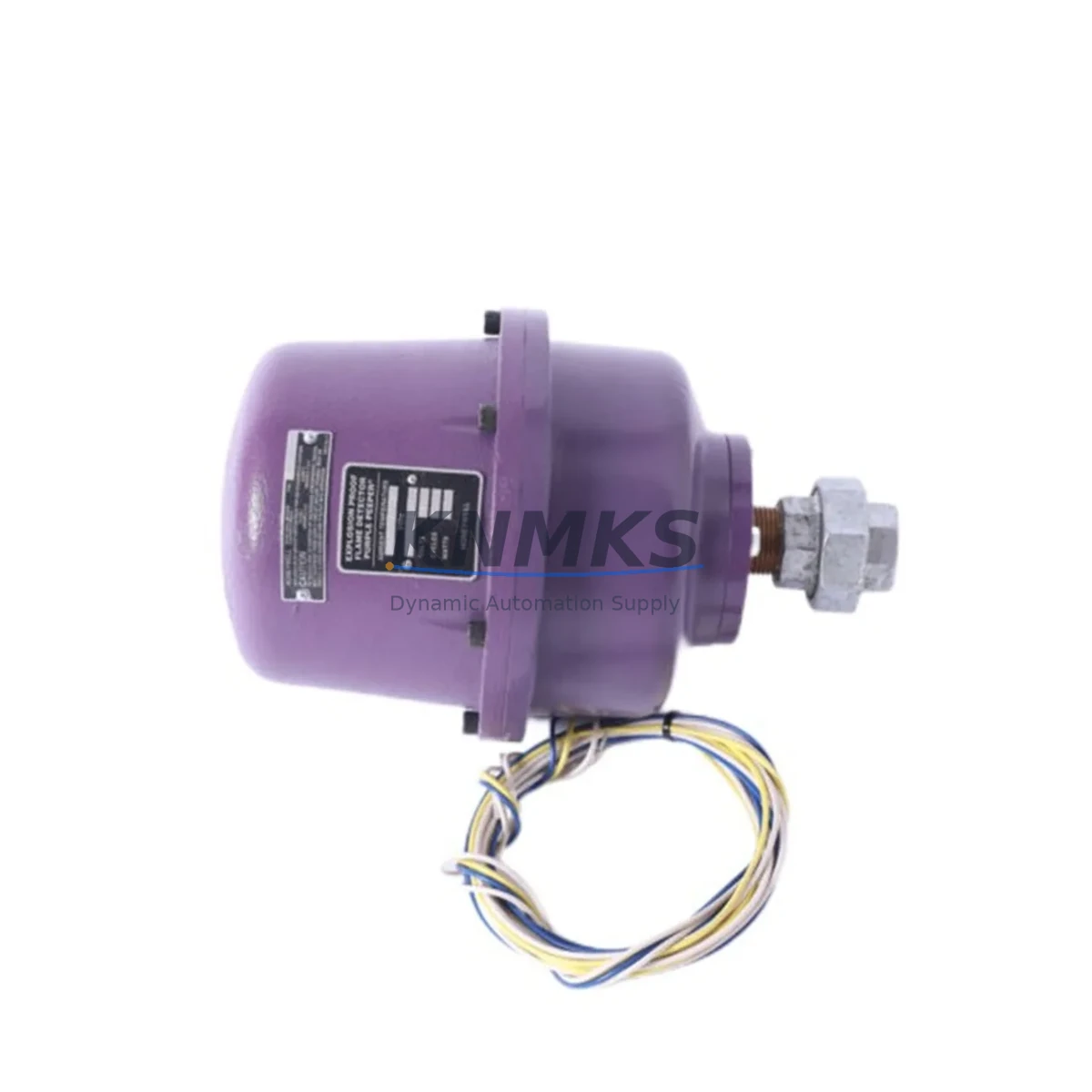
The Honeywell C7061F2001 is a migration-ready ultraviolet (UV) flame detector engineered for direct integration into Honeywell RM7800 series Burner Management Systems (BMS). As legacy combustion control platforms approach end-of-life and original spare parts become increasingly scarce, the C7061F2001 serves as a verified drop-in replacement for discontinued UV scanner models, enabling plant engineers and maintenance teams to extend the operational life of existing control cabinets without committing to a full system overhaul.
This detector is purpose-built for industrial burner applications where flame signal reliability is non-negotiable. Whether you are retrofitting a single burner control loop or upgrading an entire boiler room automation system, the C7061F2001 provides the spectral sensitivity, response time, and signal output characteristics required by the RM7800L, RM7800G, and RM7840 relay modules. Its UV sensing element responds to the 185–260 nm wavelength range, ensuring reliable flame discrimination in heavy fuel oil, natural gas, and dual-fuel burner environments.
Migration Compatibility Table
| Parameter | C7061F2001 (Replacement) | Legacy Models (Replaced) |
|---|---|---|
| Compatible Relay Module | RM7800L, RM7800G, RM7840L | R7847A1082, R7848A1006 |
| Sensing Technology | Ultraviolet (UV), 185–260 nm | UV (same spectral range) |
| Signal Output | Pulse rate signal to amplifier | Pulse rate signal to amplifier |
| Mounting Interface | Standard 1-inch NPT sight pipe thread | 1-inch NPT (direct swap) |
| Operating Temperature | –40°C to +60°C | –40°C to +60°C |
| Wiring Terminals | 2-wire connection to amplifier base | 2-wire (no rewiring required) |
| Communication Protocol | Analog pulse signal (no fieldbus) | Analog pulse signal |
| Installation Space | Identical form factor to legacy unit | Same sight pipe position |
| Firmware / Configuration | No firmware — hardware-only device | No firmware required |
| Commissioning Requirement | Flame signal verification via RM7800 display | Same commissioning procedure |
| Replacement Recommendation | Direct replacement; no adapter required | — |
| Support terms | support terms confirmed by quotation | — |
Retrofit Planning for Existing Automation Systems
Successful integration of the C7061F2001 into a legacy burner management system requires a structured retrofit assessment before any physical swap is performed. The first step is to confirm that the existing RM7800 relay module — whether an RM7800L1018, RM7800G1006, or RM7840L1018 — is operating within its rated service life and that its internal amplifier circuit is capable of correctly interpreting the UV pulse signal from the new detector. In many aging control cabinets, the relay module itself may require concurrent replacement, and the R7847C1082 or R7848A1006 amplifier sub-assembly should be inspected for contact wear and capacitor degradation before the new scanner is installed.
Terminal wiring is a critical checkpoint. The C7061F2001 uses a standard 2-wire connection routed back to the amplifier base on the RM7800 chassis. Engineers should verify that the existing field wiring — typically 18 AWG shielded twisted pair — is free of insulation breakdown and that terminal block connections at the control cabinet are torqued to specification. In older installations where the wiring harness has been in service for more than 15 years, proactive replacement of the interconnecting cable between the scanner and the amplifier base is strongly recommended to prevent intermittent flame signal faults after commissioning.
For plants operating multi-burner systems, the C7061F2001 retrofit often coincides with a broader I/O audit. Digital input modules feeding the plant DCS or SCADA system — such as those in the Honeywell HC900 hybrid controller platform — should be verified to confirm that the flame proven signal from the RM7800 is correctly mapped to the process historian and alarm management system. If the burner control loop is supervised by a Honeywell Safety Manager or a third-party safety PLC, the SIL-rated interlock logic referencing the flame signal must be reviewed and re-validated after the scanner replacement to maintain functional safety compliance.
Power supply capacity within the control cabinet is another factor that is frequently overlooked during scanner retrofits. The RM7800 series draws its operating power from a dedicated 120 VAC or 230 VAC supply circuit, and the C7061F2001 scanner itself is a passive device powered through the amplifier base — meaning no additional power budget is required for the scanner alone. However, if the retrofit is being performed as part of a wider cabinet upgrade that includes adding a new Honeywell DIN-rail power supply module, a communication gateway for Modbus RTU or BACnet MS/TP integration, or additional I/O terminal blocks, the total panel load must be recalculated to ensure the existing circuit breaker and transformer ratings are not exceeded.
Sight pipe alignment and optical path cleanliness are mechanical prerequisites that directly affect post-installation performance. Before mounting the C7061F2001, the sight pipe bore should be inspected for soot accumulation, moisture ingress, or physical obstruction. A contaminated sight pipe will attenuate the UV signal reaching the detector element and may cause nuisance lockouts or delayed flame recognition — both of which increase burner restart cycles and accelerate wear on the RM7800 relay contacts. Purge air connections, where fitted, should be verified to be delivering clean, dry instrument air at the correct flow rate prior to commissioning.
Downtime Control During System Migration
Minimizing unplanned downtime during a UV flame detector replacement is achievable through disciplined pre-staging and a clearly defined commissioning sequence. Before the burner is taken offline, the replacement C7061F2001 should be bench-tested by connecting it to a portable UV light source and confirming that the pulse output is within the expected range for the RM7800 amplifier. This pre-departure test eliminates the risk of installing a defective unit and discovering the fault only after the burner has been shut down and the production line is waiting for restart.
The physical swap itself — disconnecting the legacy scanner from the sight pipe, threading in the C7061F2001, and reconnecting the 2-wire terminal leads — can typically be completed in under 30 minutes by a qualified instrumentation technician. The RM7800 relay module does not require reprogramming or parameter reconfiguration when the replacement scanner is of the same model family, which means the existing burner control sequence, purge timing, ignition trial period, and lockout logic remain fully intact. No changes to the HMI display configuration or alarm setpoints are required, and the operator interface — whether a local panel-mounted display or a remote SCADA workstation — will continue to receive the same flame status signals without modification.
Post-installation commissioning should follow the standard RM7800 startup procedure: confirm power supply voltage at the relay module terminals, initiate a manual burner start sequence, verify that the flame signal LED on the RM7800 front panel illuminates within the expected trial-for-ignition period, and document the measured flame signal strength using the RM7800 diagnostic display or a compatible handheld programmer. A minimum of three consecutive successful start-stop cycles should be completed and recorded before the burner is returned to automatic control. This commissioning record serves as the baseline reference for future preventive maintenance inspections and supports the support terms confirmed by quotation claim process if a field issue arises.
For facilities operating continuous processes where even a brief burner outage has significant production impact, a pre-positioned spare C7061F2001 held in the site instrument store provides the fastest possible mean time to repair. Given the extended lead times historically associated with Honeywell combustion control spare parts, maintaining at least one unit of on-site inventory is a standard recommendation for any plant operating more than two RM7800-controlled burners.
Retrofit Support FAQ
Q1: Is the C7061F2001 a direct replacement for the R7847A1082 UV amplifier/scanner assembly?
The C7061F2001 is the scanner (detector) component and is designed to work with the R7847 and R7848 series amplifier bases mounted on the RM7800 relay module. It replaces the UV sensing head only — the amplifier base remains in place. If the amplifier base is also faulty, it should be replaced separately before installing the new scanner.
Q2: Does replacing the C7061F2001 require any changes to the RM7800 program or timing parameters?
No. The C7061F2001 is a hardware-only device with no configurable parameters. The RM7800 relay module retains all existing timing, sequencing, and lockout settings after the scanner is replaced. No re-commissioning of the relay module logic is required, though a full functional test of the burner start sequence is always recommended after any component replacement.
Q3: What wiring checks should be performed before installing the replacement scanner?
Verify continuity and insulation resistance of the 2-wire cable between the scanner mounting position and the amplifier base terminals on the RM7800. Check terminal block connections for corrosion or loose crimps. Confirm that the shield drain wire is grounded at one end only (typically at the control cabinet end) to prevent ground loop interference with the UV pulse signal.
Q4: What does the support terms confirmed by quotation cover, and how is it supported?
All C7061F2001 units supplied by KNMKS are covered by a support terms confirmed by quotation against manufacturing defects and premature failure under normal operating conditions. Each unit is functionally tested prior to shipment. In the event of a support terms claim, contact admin@knmks.com with the order reference and a description of the fault. Replacement units are dispatched from in-stock inventory to minimize site downtime. Support terms does not cover damage resulting from incorrect installation, sight pipe contamination, or operation outside the rated temperature and voltage specifications.
© 2026 KNMKS. All rights reserved.
Original Source: https://knmks.com
Contact: admin@knmks.com | +86 18359268345
Product Identification
- Brand / Ecosystem
-
Honeywell
Honeywell - Model / Series
- C7061F2001
- Product Family
- Sensors
- Availability Status
- Available on request after model and quantity confirmation
- Inquiry Type
- B2B RFQ, replacement inquiry and project spare-part request
- Pre-Quote Check
- Exact SKU, brand, series, quantity, nameplate photos and destination country are checked before quotation
System Path
Where this product fits in the KNMKS automation structure.
Specification & Inquiry Focus
- Sensor range
- Photoelectric, proximity and process sensors
- Common needs
- Output type, distance and connector
- Project support
- Machine detection and replacement inquiry
Buyer Confirmation
Information KNMKS checks before replying.
- Exact model
- C7061F2001
- Brand / ecosystem
- Honeywell
- Product family
- Sensors
- Application note
- Replacement, maintenance, project build or spare-part list
- Useful photos
- Nameplate, installed unit, cabinet layout or connector side
- Delivery details
- Quantity, destination country and target schedule
Document Support
Files and notes can be confirmed during quotation.
- Product photos or nameplate confirmation when available
- Packing and delivery notes before quotation confirmation
- Support scope and delivery terms confirmed per inquiry
- Export document coordination for qualified B2B requests
Inquiry Support
- NPN/PNP, analog and digital output checking
- Connector and cable compatibility review
- Fast inquiry support for maintenance teams
What to Send Us
- Brand and exact model number: Honeywell C7061F2001
- Quantity and required delivery time
- Application, replacement requirement or nameplate photo
- Destination country and shipping preference
RFQ Preparation
This is a product inquiry page built for RFQ communication.
Fast Model Check
Send this model to KNMKS for confirmation.
Include quantity, destination country and photos if this is a maintenance replacement. The inquiry will be saved with a reference number after submission.
Brand & Compatibility Note
KNMKS displays automation product information for well-known industrial brand ecosystems and compatible replacement references. Brand names are used for product identification and compatibility reference only; final availability and commercial terms are confirmed per quotation.
 Manufacturing
 Machine Tools
 Packaging
 Energy & Power
 PLCs & Controllers
 HMI & Displays
 Servo Systems
 Variable Frequency Drives