
Overview
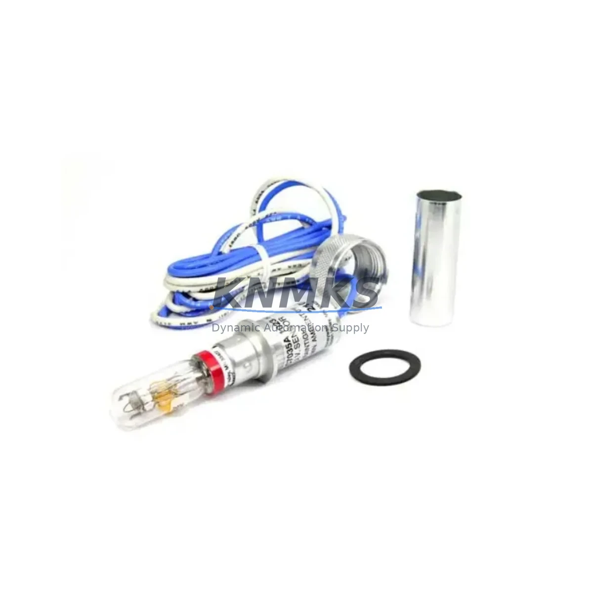
Honeywell C7035A1023 Maintenance-Proven Spare Part for Factory Uptime
The Honeywell C7035A1023 (cross-reference: C7035A1064) is a UV flame sensor engineered for continuous-duty combustion monitoring in industrial burner control systems. Designed for integration with Honeywell’s C7035 series flame amplifiers and burner management controllers, this sensor delivers reliable ultraviolet flame detection across boiler plants, furnace lines, process heaters, and thermal oxidizers. For maintenance engineers managing scheduled shutdowns or emergency flame-failure events, stocking a verified C7035A1023 spare eliminates the risk of extended downtime caused by OEM lead times that can stretch 8–16 weeks on legacy combustion components.
At KNMKS, every C7035A1023 unit is pre-shipment tested against Honeywell’s original electrical and optical specifications. Each spare ships with a support terms confirmed by quotation covering manufacturing defects and functional performance, supporting your site’s spare parts governance and audit requirements.
Spare Maintenance Table
| Parameter | Specification |
|---|---|
| Part Number | C7035A1023 (Cross-ref: C7035A1064) |
| Brand | Honeywell |
| Series | C7035 |
| Product Type | UV Flame Sensor |
| Detection Method | Ultraviolet (UV) flame detection |
| Compatible Controllers | Honeywell R4343, R7847, R7848, R7849 Flame Amplifiers; BC1000 / RM7800 Series Burner Management |
| Supply Voltage | 120 VAC / 240 VAC (controller-powered) |
| Operating Temperature | -40°C to +70°C ambient |
| Flame Signal Output | DC microamp signal to amplifier module |
| Mounting | Threaded sight pipe, 1-inch NPT compatible |
| Country of Origin | Germany (DE) |
| Weight | 160 g |
| Application | Boilers, furnaces, process heaters, thermal oxidizers, incinerators |
| Support terms | 12 Months — manufacturing defect and functional performance |
| Condition | Original, new-in-box; pre-shipment tested |
| Dispatch | Global — multi-region stock, rapid dispatch |
Maintenance Planning for Continuous Operation
UV flame sensors are a critical wear component in any combustion safety loop. The C7035A1023 operates in high-temperature, vibration-prone environments where UV tube degradation, contaminated sight pipes, and loose signal wiring are the primary failure modes. A structured maintenance plan should treat this sensor as a consumable with a defined replacement interval — typically 18–36 months depending on duty cycle and burner firing frequency.
When replacing the C7035A1023 on-site, maintenance engineers should simultaneously inspect the following components to prevent repeat call-outs and ensure the combustion control loop is fully restored:
- Honeywell R7847 or R7848 Flame Amplifier Module: The amplifier interprets the UV sensor’s microamp signal. A degraded amplifier can mask a healthy sensor reading or generate nuisance lockouts. Verify amplifier sensitivity settings and check for moisture ingress or terminal corrosion.
- RM7800 Series Burner Management Controller: Confirm that the burner management relay sequence — pre-purge, ignition trial, flame-on confirmation — is executing correctly after sensor replacement. Faulty relay contacts or a corrupted program module can cause repeated flame-failure faults even with a new sensor installed.
- Sight Pipe and Optical Path: Carbon deposits, soot, or condensation inside the sight pipe will attenuate the UV signal. Clean and inspect the sight pipe bore before installing the replacement C7035A1023. A contaminated optical path is the most common cause of premature sensor failure.
- Signal Wiring and Terminal Blocks: Inspect the low-voltage signal cable between the sensor and amplifier for insulation damage, loose ferrules, or incorrect routing near high-voltage ignition cables. EMI-induced noise on the signal line can cause erratic flame readings. Use shielded cable where possible and verify terminal block torque values.
- Ignition Transformer and Electrode Assembly: A weak ignition spark reduces the UV intensity during the ignition trial, which can cause the sensor to fail to confirm flame even when combustion is occurring. Inspect electrode gap, ceramic insulation, and transformer output voltage as part of the same maintenance event.
- Control Panel Fusing and Power Supply: Verify that the 24 VDC or 120 VAC supply rail feeding the burner management controller and flame amplifier is within tolerance. Blown fuses or a failing DIN-rail power supply can cause intermittent flame-failure faults that are incorrectly attributed to the sensor.
For facilities operating multiple burner lines or boiler trains, maintaining a minimum buffer of two C7035A1023 units per site — alongside matched R7847 amplifier modules and RM7800 controller spares — is recommended to support emergency replacement without waiting for inbound shipments.
Site Replacement Workflow
The C7035A1023 is a direct replacement for the C7035A1064 and is backward-compatible with all C7035 series sight-pipe mounting configurations. Follow this workflow to minimize downtime during an unplanned flame-failure event:
- Isolate and Lock Out: Follow site LOTO procedures. De-energize the burner management panel and confirm zero-energy state before accessing the sensor sight pipe.
- Remove the Failed Sensor: Unscrew the C7035A1023 from the sight pipe fitting. Inspect the sight pipe bore for deposits and clean with a dry lint-free cloth or compressed air.
- Install Replacement Unit: Thread the new C7035A1023 into the sight pipe. Do not overtighten — hand-tight plus one-quarter turn is sufficient for the NPT fitting. Reconnect the signal cable to the amplifier terminal block, observing correct polarity.
- Restore Power and Verify Signal: Re-energize the panel. Using the flame amplifier’s signal strength indicator or a calibrated microammeter, verify that the UV signal is within the amplifier’s acceptance window during the ignition trial.
- Confirm Burner Sequence: Run a complete burner start sequence — pre-purge, ignition trial, flame-on — and confirm that the burner management controller advances through all stages without lockout.
- Document and Update Maintenance Log: Record the replacement date, unit serial number, and post-installation signal reading in the site maintenance log. Update the spare parts inventory to trigger reorder of the consumed unit.
This workflow applies equally to planned annual overhauls and emergency call-outs, and is compatible with Honeywell’s recommended commissioning procedure for C7035 series sensors.
Spare Parts Support FAQ
Q1: Is the C7035A1023 a direct replacement for the C7035A1064?
Yes. The C7035A1023 and C7035A1064 are functionally equivalent UV flame sensors within the Honeywell C7035 series. Both share the same mounting dimensions, signal output characteristics, and amplifier compatibility. Either part number can be used as a drop-in replacement for the other without modification to the sight pipe, wiring, or amplifier sensitivity settings.
Q2: What pre-shipment testing is performed on each unit?
Every C7035A1023 supplied by KNMKS undergoes electrical continuity verification, UV tube integrity check, and functional signal output confirmation before dispatch. Units that do not meet Honeywell’s original specification thresholds are quarantined and not shipped. A test record is available upon request for quality audit purposes.
Q3: What does the support terms confirmed by quotation cover?
The support terms confirmed by quotation cover manufacturing defects and functional performance failure under normal operating conditions. It does not cover damage resulting from incorrect installation, sight pipe contamination, overvoltage events, or mechanical impact. Support requests are processed directly through KNMKS with replacement dispatch typically within 3–5 business days of claim confirmation.
Q4: Can KNMKS support long-term or blanket purchase orders for C7035A1023?
Yes. KNMKS supports long-term supply agreements and blanket PO arrangements for facilities requiring guaranteed stock availability across multiple maintenance cycles. Contact our sales team to discuss volume pricing, consignment stock options, and scheduled delivery programs tailored to your annual maintenance calendar.
© 2026 KNMKS. All rights reserved.
Original Source: https://knmks.com
Contact: admin@knmks.com | +86 18359268345
Product Identification
- Brand / Ecosystem
-
Honeywell
Honeywell - Model / Series
- C7035A1023 C7035A1064
- Product Family
- Sensors
- Availability Status
- Available on request after model and quantity confirmation
- Inquiry Type
- B2B RFQ, replacement inquiry and project spare-part request
- Pre-Quote Check
- Exact SKU, brand, series, quantity, nameplate photos and destination country are checked before quotation
System Path
Where this product fits in the KNMKS automation structure.
Specification & Inquiry Focus
- Sensor range
- Photoelectric, proximity and process sensors
- Common needs
- Output type, distance and connector
- Project support
- Machine detection and replacement inquiry
Buyer Confirmation
Information KNMKS checks before replying.
- Exact model
- C7035A1023 C7035A1064
- Brand / ecosystem
- Honeywell
- Product family
- Sensors
- Application note
- Replacement, maintenance, project build or spare-part list
- Useful photos
- Nameplate, installed unit, cabinet layout or connector side
- Delivery details
- Quantity, destination country and target schedule
Document Support
Files and notes can be confirmed during quotation.
- Product photos or nameplate confirmation when available
- Packing and delivery notes before quotation confirmation
- Support scope and delivery terms confirmed per inquiry
- Export document coordination for qualified B2B requests
Inquiry Support
- NPN/PNP, analog and digital output checking
- Connector and cable compatibility review
- Fast inquiry support for maintenance teams
What to Send Us
- Brand and exact model number: Honeywell C7035A1023 C7035A1064
- Quantity and required delivery time
- Application, replacement requirement or nameplate photo
- Destination country and shipping preference
RFQ Preparation
This is a product inquiry page built for RFQ communication.
Fast Model Check
Send this model to KNMKS for confirmation.
Include quantity, destination country and photos if this is a maintenance replacement. The inquiry will be saved with a reference number after submission.
Brand & Compatibility Note
KNMKS displays automation product information for well-known industrial brand ecosystems and compatible replacement references. Brand names are used for product identification and compatibility reference only; final availability and commercial terms are confirmed per quotation.
 Manufacturing
 Machine Tools
 Packaging
 Energy & Power
 PLCs & Controllers
 HMI & Displays
 Servo Systems
 Variable Frequency Drives