
Overview
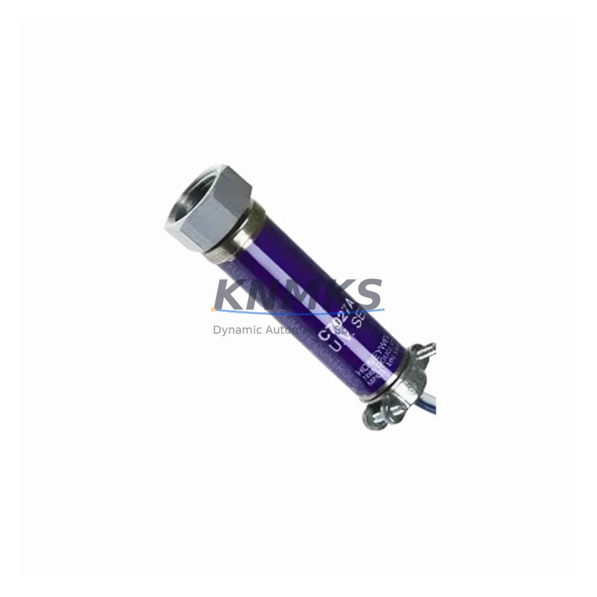
Honeywell C7027A1064 Maintenance-Proven Spare Part for Factory Uptime
The Honeywell C7027A1064 is an original UV flame sensor engineered for continuous-duty burner management in industrial combustion systems. Designed for the C7027 Series, this sensor provides reliable ultraviolet flame detection across a broad range of industrial burner control applications — including boilers, furnaces, process heaters, and thermal oxidizers. For maintenance engineers managing scheduled inspections or emergency shutdowns, having a verified C7027A1064 spare on the shelf is a direct investment in production continuity.
UV flame sensors are among the highest-wear components in any combustion control loop. Exposure to heat cycling, vibration, and UV flux degradation means that the C7027A1064 should be treated as a consumable maintenance item — not a reactive replacement. Procurement engineers sourcing for annual MRO budgets should plan for at least one unit per burner train, with additional buffer stock for multi-burner installations or remote sites with extended lead times.
This listing covers the C7027A1064 and its functionally equivalent variant C7027A1072, both of which are direct-fit replacements within the C7027 Series flame detector family. All units are pre-shipment tested, dispatched with original manufacturer packaging where available, and covered by a support terms confirmed by quotation from the date of invoice.
Spare Maintenance Table
| SKU | C7027A1064 / C7027A1072 |
| Brand | Honeywell |
| Series | C7027 |
| Product Type | UV Flame Sensor / Flame Detector |
| Detection Method | Ultraviolet (UV) flame detection |
| Compatible Controllers | Honeywell R7847, R7849, R7861, RM7800 Series Burner Controllers |
| Mounting | Standard 1-inch NPT threaded fitting; direct-mount to sight tube |
| Operating Temperature | Up to 125°C (257°F) ambient at sensor body |
| Supply Voltage | 120 VAC / 240 VAC (controller-supplied) |
| Output Signal | Flame relay signal to burner management controller |
| Application Environment | Industrial boilers, furnaces, process heaters, thermal oxidizers |
| Origin | United States |
| Compatibility Note | Verify sight tube alignment and amplifier card compatibility before installation |
| Maintenance Interval | Inspect every 6 months; replace at first sign of UV response degradation |
| Pre-Shipment Test | Yes — functional UV response verified before dispatch |
| Support terms | 12 months from invoice date |
Maintenance Planning for Continuous Operation
When replacing the C7027A1064 during a scheduled outage or emergency callout, a disciplined maintenance engineer will not stop at the sensor alone. The C7027 Series sensor operates as part of a tightly integrated combustion safety loop, and adjacent components should be inspected or replaced concurrently to prevent repeat failures and unplanned downtime.
Begin with the Honeywell R7847 or R7849 amplifier card — the UV signal from the C7027A1064 is processed by the amplifier module seated in the burner controller chassis. A degraded amplifier card can mask a healthy sensor or generate nuisance lockouts. If the C7027A1064 is being replaced due to repeated flame-failure faults, the amplifier card should be swapped simultaneously. Next, inspect the RM7800 Series burner management controller itself: check terminal block connections, verify that the flame relay output is responding correctly, and confirm that the controller’s self-check cycle completes without fault codes.
The sight tube and UV window are frequently overlooked. Soot accumulation or UV-absorbing deposits on the sight glass will attenuate the UV signal even with a new sensor installed — clean or replace the sight tube assembly as part of every C7027A1064 swap. For installations with high particulate environments, consider adding a purge air fitting to the sight tube to extend sensor service life.
On the electrical side, inspect the sensor cable and connector for heat damage, insulation cracking, or corroded pins. A high-resistance connection between the C7027A1064 and the amplifier card is a common source of intermittent flame-failure alarms. Replace the cable if any discoloration or mechanical damage is visible. Also verify the control panel fusing — the circuit supplying the burner controller and flame detection loop should be protected by correctly rated fuses or circuit breakers; check for signs of thermal stress or nuisance tripping.
For sites running multiple burner trains, it is sound practice to maintain a dedicated spare kit that includes the C7027A1064 sensor, a spare amplifier card, a replacement sight tube, and a pre-cut sensor cable assembly. This approach reduces mean time to repair (MTTR) from hours to minutes and eliminates the risk of sourcing delays during a production emergency.
Site Replacement Workflow
Step 1 — Isolation: Place the burner management system in lockout/tagout (LOTO) state. Confirm that the burner is fully purged and that the RM7800 controller is de-energized before accessing the flame sensor.
Step 2 — Sensor Removal: Disconnect the sensor cable at the amplifier card. Unscrew the C7027A1064 from the sight tube fitting using the appropriate spanner. Note the orientation of the sensor body relative to the flame axis — the replacement must be installed at the same angle.
Step 3 — Sight Tube Inspection: Before installing the new C7027A1064, inspect the sight tube bore for soot, scale, or UV window fouling. Clean with a dry lint-free cloth. If the UV window is cracked or heavily discolored, replace the sight tube assembly before proceeding.
Step 4 — Sensor Installation: Thread the new C7027A1064 into the sight tube fitting. Do not overtighten — finger-tight plus one-quarter turn is sufficient for a gas-tight seal on a properly conditioned NPT thread. Reconnect the sensor cable to the amplifier card, ensuring the connector is fully seated and the locking tab is engaged.
Step 5 — Functional Verification: Re-energize the burner controller and initiate a controlled burner start. Confirm that the C7027A1064 generates a valid flame signal within the controller’s flame-establishment period. Check the amplifier card indicator LED (if fitted) and verify that the burner management controller exits the ignition sequence and enters the run state without lockout.
Step 6 — Documentation: Record the replacement date, new sensor serial number, and post-installation test result in the equipment maintenance log. Update the spare parts inventory to trigger reorder of the consumed C7027A1064 unit.
This workflow applies equally to legacy installations using older Honeywell burner controller models. The C7027A1064 is backward-compatible with earlier C7027 Series amplifier cards, making it a reliable long-term replacement option for aging combustion systems without requiring controller upgrades.
Spare Parts Support FAQ
Q1: Is the C7027A1064 a direct replacement for the C7027A1072?
Yes. The C7027A1064 and C7027A1072 are functionally equivalent within the C7027 Series. Both units use the same UV detection element, the same 1-inch NPT mounting thread, and the same amplifier card interface. Either part number can be used as a drop-in replacement for the other without any wiring or configuration changes.
Q2: How is the C7027A1064 tested before shipment?
Every unit is functionally verified for UV response prior to dispatch. We do not ship untested stock. Units that fail pre-shipment verification are quarantined and not offered for sale. Test records are retained internally and can be referenced in the event of a support terms claim.
Q3: What is the recommended spare stock level for a multi-burner installation?
For installations with two to four burner trains, we recommend maintaining a minimum of two C7027A1064 units on-site at all times. For larger installations or sites with extended resupply lead times (remote locations, offshore platforms), a buffer of one unit per burner train plus one additional unit is a sound baseline. Annual MRO procurement should account for the sensor’s typical service interval of 12–18 months under normal operating conditions.
Q4: What support terms coverage applies to the C7027A1064?
All C7027A1064 units supplied by KNMKS carry a support terms confirmed by quotation from the date of invoice. Support terms coverage includes defects in materials and workmanship under normal operating conditions. Units that fail within the confirmed support period due to manufacturing defects will be replaced or credited at our discretion. Support requests require the original invoice number and a brief description of the failure mode. Contact admin@knmks.com to initiate a support terms claim.
© 2026 KNMKS. All rights reserved.
Original Source: https://knmks.com
Contact: admin@knmks.com | +86 18359268345
Product Identification
- Brand / Ecosystem
-
Honeywell
Honeywell - Model / Series
- C7027A1064/C7027A1072
- Product Family
- Sensors
- Availability Status
- Available on request after model and quantity confirmation
- Inquiry Type
- B2B RFQ, replacement inquiry and project spare-part request
- Pre-Quote Check
- Exact SKU, brand, series, quantity, nameplate photos and destination country are checked before quotation
System Path
Where this product fits in the KNMKS automation structure.
Specification & Inquiry Focus
- Sensor range
- Photoelectric, proximity and process sensors
- Common needs
- Output type, distance and connector
- Project support
- Machine detection and replacement inquiry
Buyer Confirmation
Information KNMKS checks before replying.
- Exact model
- C7027A1064/C7027A1072
- Brand / ecosystem
- Honeywell
- Product family
- Sensors
- Application note
- Replacement, maintenance, project build or spare-part list
- Useful photos
- Nameplate, installed unit, cabinet layout or connector side
- Delivery details
- Quantity, destination country and target schedule
Document Support
Files and notes can be confirmed during quotation.
- Product photos or nameplate confirmation when available
- Packing and delivery notes before quotation confirmation
- Support scope and delivery terms confirmed per inquiry
- Export document coordination for qualified B2B requests
Inquiry Support
- NPN/PNP, analog and digital output checking
- Connector and cable compatibility review
- Fast inquiry support for maintenance teams
What to Send Us
- Brand and exact model number: Honeywell C7027A1064/C7027A1072
- Quantity and required delivery time
- Application, replacement requirement or nameplate photo
- Destination country and shipping preference
RFQ Preparation
This is a product inquiry page built for RFQ communication.
Fast Model Check
Send this model to KNMKS for confirmation.
Include quantity, destination country and photos if this is a maintenance replacement. The inquiry will be saved with a reference number after submission.
Brand & Compatibility Note
KNMKS displays automation product information for well-known industrial brand ecosystems and compatible replacement references. Brand names are used for product identification and compatibility reference only; final availability and commercial terms are confirmed per quotation.
 Manufacturing
 Machine Tools
 Packaging
 Energy & Power
 PLCs & Controllers
 HMI & Displays
 Servo Systems
 Variable Frequency Drives