
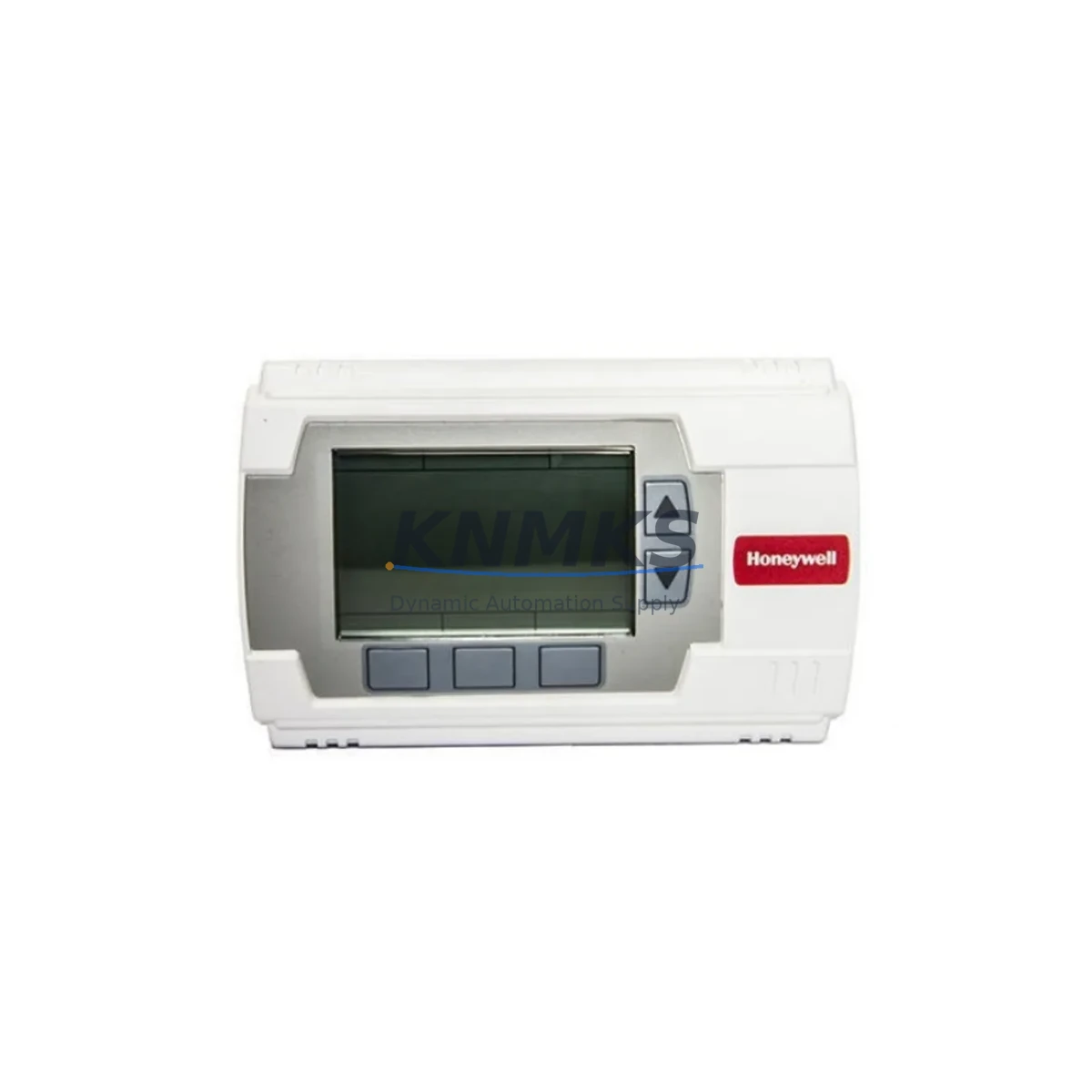
Overview
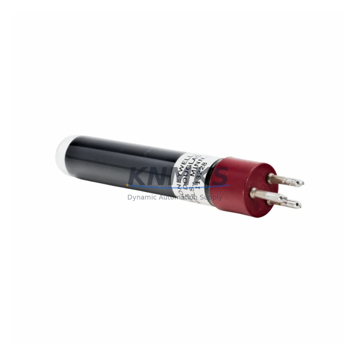
Honeywell C7027A1049 Migration-Ready UV Flame Sensor for Legacy Control Systems
The Honeywell C7027A1049 is a UV flame detector engineered for direct integration into legacy burner management systems (BMS) and combustion control panels where the original C7027A series sensors have reached end-of-life or are no longer available through standard OEM channels. As industrial facilities face increasing pressure to maintain uptime on aging thermal processing lines, boiler rooms, and fired heater skids, the C7027A1049 provides a migration-ready solution that preserves existing wiring infrastructure, relay logic, and flame amplifier compatibility without requiring a full control system overhaul.
Designed for use with Honeywell R7847 and R7848 flame amplifier modules, the C7027A1049 operates on ultraviolet detection principles, offering reliable flame presence confirmation across a broad range of fuel types including natural gas, light oil, and dual-fuel burner configurations. Its compact cylindrical housing and standard 1/2-inch NPT mounting thread allow direct substitution into existing sensor ports on burner management panels, minimizing installation time and reducing the risk of wiring errors during changeover. Engineers performing a controlled retrofit can retain the existing conduit runs, terminal block assignments, and amplifier card slots, significantly reducing downtime exposure during the transition window.
When planning a C7027A1049 installation as part of a broader BMS modernization, technicians should verify the supply voltage to the flame amplifier — typically 120 VAC or 24 VAC depending on the panel generation — and confirm that the amplifier’s UV sensitivity threshold is correctly calibrated for the new sensor’s spectral response. Terminal wiring should be cross-referenced against the original C7027A wiring diagram, paying particular attention to the signal return path and shield grounding at the amplifier input. Where the existing panel includes a Honeywell R4795 or R4140 primary control, compatibility with the C7027A1049 signal output should be confirmed prior to energizing the burner circuit.
Migration Compatibility Table
| Parameter | C7027A1049 Specification | Retrofit Notes |
|---|---|---|
| Detection Method | Ultraviolet (UV) | Replaces C7027A, C7027B series UV sensors directly |
| Compatible Amplifiers | R7847A, R7848A | Verify amplifier firmware version before substitution |
| Mounting Thread | 1/2-inch NPT | Direct drop-in; no adapter required for standard ports |
| Signal Output | UV current signal to amplifier | Confirm shield grounding at amplifier terminal |
| Operating Temperature | -40°C to +60°C | Verify ambient temperature at sensor mounting location |
| Primary Control Compatibility | R4795, R4140, RM7800 series | Cross-check relay logic and lockout reset sequence |
| Communication Protocol | Hardwired analog signal | No protocol migration required; retain existing wiring |
| Installation Space | Standard cylindrical sensor body | Confirm clearance in burner head or sight tube assembly |
| Commissioning Requirement | Flame signal strength check via amplifier test point | Perform UV signal verification before returning to service |
| Support terms | 12 Months | Covered from date of dispatch; pre-shipment tested |
Retrofit Planning for Existing Automation Systems
A successful C7027A1049 retrofit begins well before the physical sensor swap. Maintenance engineers should audit the full burner management loop, starting from the flame amplifier — typically a Honeywell R7847A1075 or R7848A1017 — and tracing back through the primary control relay, ignition transformer, and fuel valve interlock circuit. Where the existing system uses a Honeywell RM7800L or RM7840L burner control module, the C7027A1049 integrates directly into the UV input circuit without requiring changes to the control program or safety relay configuration.
For panels that include a Honeywell Q7800A or Q7800B subbase assembly, technicians should confirm that the sensor cable routing does not introduce ground loops that could cause nuisance flame-out trips. In multi-burner installations where several C7027A sensors are being replaced simultaneously, it is advisable to stage the replacement one burner at a time, retaining at least one proven sensor in service while the new units are commissioned. This approach is particularly important in continuous process applications — such as fired heaters on refinery units or direct-fired dryers in food processing — where a simultaneous multi-burner outage would trigger a full process shutdown.
Where the retrofit scope extends beyond the flame sensor itself, engineers may also need to evaluate the condition of the associated Honeywell C7012E or C7012F UV scanner assemblies, the burner management panel’s terminal block wiring, and the integrity of the sensor cable and conduit seal. In some legacy installations, the original sensor cable may have degraded insulation that introduces signal noise at the amplifier input, causing intermittent flame failure alarms even after the sensor has been replaced. A full cable continuity and insulation resistance check is recommended as part of the commissioning procedure.
Downtime Control During System Migration
Minimizing production downtime during a C7027A1049 changeover requires a structured pre-outage preparation sequence. Before taking the burner offline, technicians should document the existing flame signal strength reading at the R7847 or R7848 amplifier test point, record the current lockout history from the RM7800 series control module, and photograph the existing terminal wiring at both the sensor head and the amplifier card. This baseline documentation allows rapid fault diagnosis if the new sensor does not produce an expected flame signal on first light-off.
During the physical swap, the burner circuit should be de-energized at the panel disconnect, and the fuel valve interlock should be confirmed closed before removing the existing sensor. The C7027A1049 should be installed finger-tight initially, with the sensor window aligned toward the flame zone, before final torque is applied to the NPT thread. After installation, the amplifier should be powered up in test mode — where available on the RM7800L or RM7840L — to verify UV signal presence before the full burner start sequence is initiated. This staged commissioning approach protects the original program logic in the primary control and avoids unnecessary safety lockouts that could extend the outage window.
For facilities operating under a planned maintenance window, the complete C7027A1049 replacement procedure — including sensor removal, installation, wiring verification, and flame signal commissioning — can typically be completed within two to four hours per burner, depending on access conditions and panel configuration. Pre-staging the replacement sensor, cable, and any required conduit fittings before the outage begins is the single most effective measure for compressing the actual downtime exposure.
Retrofit Support FAQ
Q: Is the C7027A1049 a direct replacement for the C7027A1033 and C7027A1025?
A: Yes. The C7027A1049 is functionally interchangeable with earlier C7027A suffix variants including the C7027A1033 and C7027A1025. The mounting thread, UV detection window, and signal output characteristics are consistent across the C7027A series. Confirm the amplifier model and wiring diagram before installation to ensure terminal assignments match.
Q: What commissioning checks are required after installing the C7027A1049?
A: After installation, verify UV signal strength at the R7847 or R7848 amplifier test point with the burner firing. The signal should fall within the amplifier’s specified acceptance range. Perform a flame failure simulation by blocking the sensor window and confirm that the amplifier drives the primary control to lockout within the specified response time. Reset and repeat the start sequence to confirm normal operation before returning the burner to automatic control.
Q: Can the existing sensor cable and conduit be reused?
A: In most cases, yes — provided the cable insulation is intact and the conductor resistance is within specification. Perform an insulation resistance test between the signal conductor and shield before reusing the existing cable. Degraded cable insulation is a common source of nuisance flame-out alarms after sensor replacement and should be ruled out before concluding commissioning.
Q: What support terms and pre-shipment testing does the C7027A1049 carry?
A: Each C7027A1049 unit is pre-shipment tested for UV detection response and electrical continuity before dispatch. A support terms confirmed by quotation is provided from the date of shipment, covering manufacturing defects and functional failures under normal operating conditions. In-stock units are available for same-day or next-business-day dispatch to minimize lead time on urgent replacement requirements.
© 2026 KNMKS. All rights reserved.
Original Source: https://knmks.com
Contact: admin@knmks.com | +86 18359268345
Product Identification
- Brand / Ecosystem
-
Honeywell
Honeywell - Model / Series
- C7027A1049
- Product Family
- Sensors
- Availability Status
- Available on request after model and quantity confirmation
- Inquiry Type
- B2B RFQ, replacement inquiry and project spare-part request
- Pre-Quote Check
- Exact SKU, brand, series, quantity, nameplate photos and destination country are checked before quotation
System Path
Where this product fits in the KNMKS automation structure.
Specification & Inquiry Focus
- Sensor range
- Photoelectric, proximity and process sensors
- Common needs
- Output type, distance and connector
- Project support
- Machine detection and replacement inquiry
Buyer Confirmation
Information KNMKS checks before replying.
- Exact model
- C7027A1049
- Brand / ecosystem
- Honeywell
- Product family
- Sensors
- Application note
- Replacement, maintenance, project build or spare-part list
- Useful photos
- Nameplate, installed unit, cabinet layout or connector side
- Delivery details
- Quantity, destination country and target schedule
Document Support
Files and notes can be confirmed during quotation.
- Product photos or nameplate confirmation when available
- Packing and delivery notes before quotation confirmation
- Support scope and delivery terms confirmed per inquiry
- Export document coordination for qualified B2B requests
Inquiry Support
- NPN/PNP, analog and digital output checking
- Connector and cable compatibility review
- Fast inquiry support for maintenance teams
What to Send Us
- Brand and exact model number: Honeywell C7027A1049
- Quantity and required delivery time
- Application, replacement requirement or nameplate photo
- Destination country and shipping preference
RFQ Preparation
This is a product inquiry page built for RFQ communication.
Fast Model Check
Send this model to KNMKS for confirmation.
Include quantity, destination country and photos if this is a maintenance replacement. The inquiry will be saved with a reference number after submission.
Brand & Compatibility Note
KNMKS displays automation product information for well-known industrial brand ecosystems and compatible replacement references. Brand names are used for product identification and compatibility reference only; final availability and commercial terms are confirmed per quotation.
 Manufacturing
 Machine Tools
 Packaging
 Energy & Power
 PLCs & Controllers
 HMI & Displays
 Servo Systems
 Variable Frequency Drives