
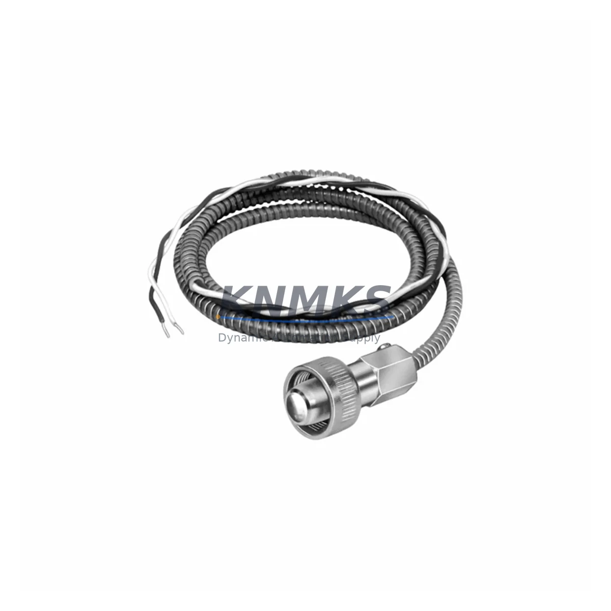
Overview
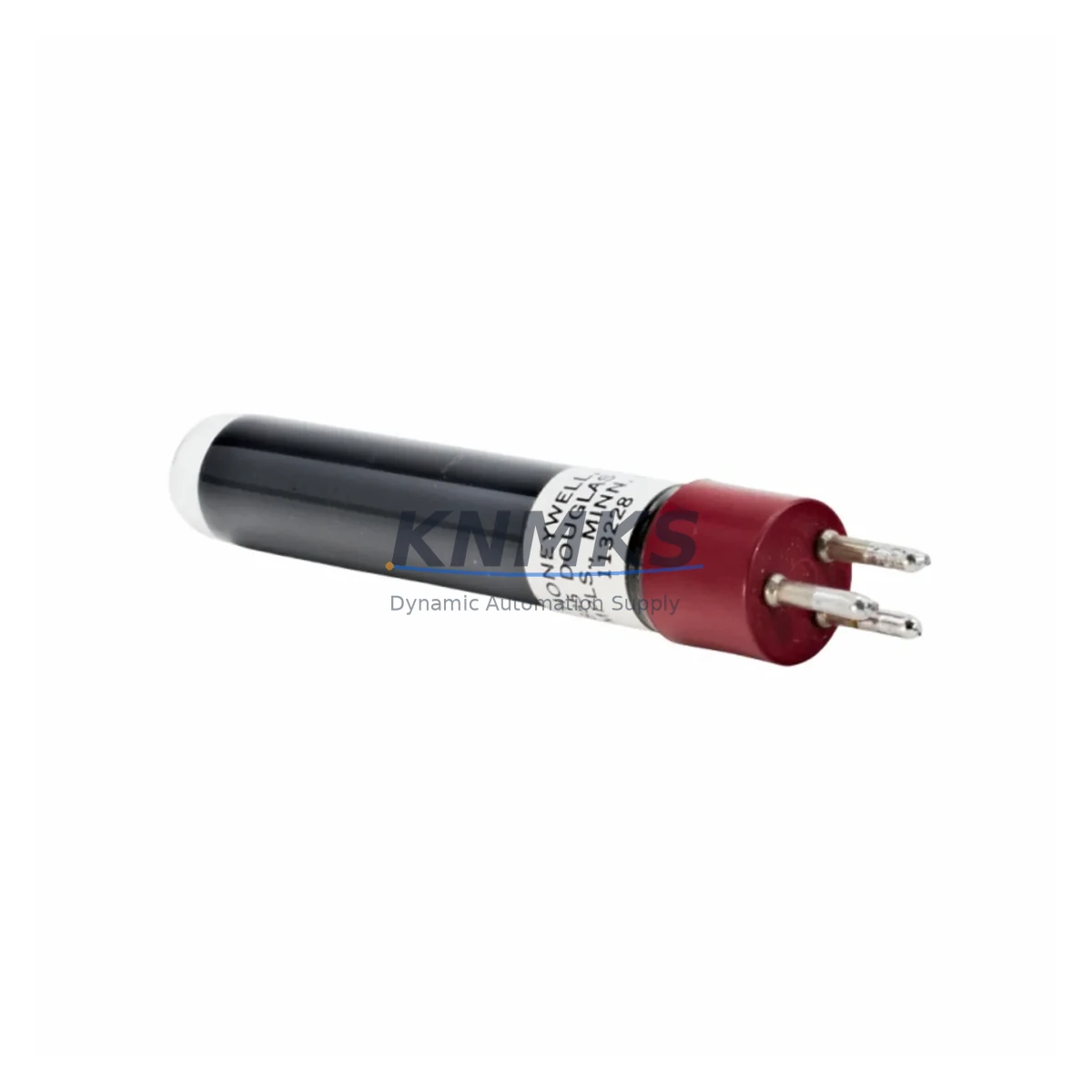
Honeywell C7015A1076 Migration-Ready UV Flame Detector for Legacy Control Systems
The Honeywell C7015A1076 is a migration-ready ultraviolet (UV) flame detector engineered as a direct replacement for end-of-life and discontinued units within the Honeywell C7015 Burner Safeguard Series. Designed for combustion control systems in industrial boilers, process heaters, thermal oxidizers, and fired equipment, this detector provides reliable flame signal output compatible with legacy Honeywell R4140, R7140, and R7184 burner controls without requiring panel rewiring or logic reprogramming. Each unit is pre-tested prior to shipment and backed by a support terms confirmed by quotation, making it the preferred choice for maintenance teams managing scheduled outages, emergency replacements, and phased modernization projects.
When replacing a failed or aging C7015 series detector, engineers must confirm several critical parameters before installation. Power supply voltage (typically 120 VAC or 240 VAC depending on the burner control model) must match the replacement unit’s rated input. Terminal wiring assignments — including the UV cell signal lead, ground, and shield connections — should be verified against the original wiring diagram to avoid nuisance trips or loss of flame signal. The detector’s mounting orientation and sight tube alignment directly affect UV sensitivity; any deviation from the original angle can result in intermittent flame failure signals during burner light-off. Firmware or relay timing settings within the associated burner control (such as the Honeywell R7140G or R7184B) should be reviewed to confirm that the flame signal response time of the C7015A1076 falls within the programmed safety timing window.
For sites operating Honeywell Slate or legacy RM7800 series flame safeguard systems, the C7015A1076 integrates directly into the existing amplifier and scanner circuit without additional signal conditioning. Where the original installation used a C7015A1014 or C7015A1032 variant, the C7015A1076 serves as the current production equivalent, maintaining identical UV spectral response and output signal characteristics. Replacement planning should also account for the condition of the sight tube assembly, UV cell socket, and any inline signal isolators — components that are frequently overlooked during detector swaps but that significantly affect long-term detection reliability.
Migration Compatibility Table
| Parameter | C7015A1076 (Replacement) | Legacy C7015A1014 / C7015A1032 | Notes |
|---|---|---|---|
| Detection Method | Ultraviolet (UV) | Ultraviolet (UV) | Direct spectral match |
| Compatible Burner Controls | R4140, R7140, R7184, RM7800 Series | R4140, R7140, R7184 | Expanded compatibility |
| Supply Voltage | 120 VAC / 240 VAC (model-dependent) | 120 VAC / 240 VAC | Confirm panel voltage before ordering |
| Terminal Wiring | Identical pin-out to C7015 series | Standard C7015 pin-out | No rewiring required |
| Mounting Interface | Standard C7015 sight tube flange | Standard C7015 sight tube flange | Confirm sight tube condition |
| Signal Output | UV cell analog signal to amplifier | UV cell analog signal to amplifier | No amplifier reconfiguration needed |
| Communication Protocol | Hardwired analog (no fieldbus) | Hardwired analog | Not applicable for protocol migration |
| Commissioning Requirement | Sight tube alignment + flame signal verification | Sight tube alignment | Verify signal strength at burner control |
| Pre-Shipment Testing | Yes — UV response verified | Varies (legacy stock) | Each unit tested before dispatch |
| Support terms | 12 Months | No support terms (discontinued) | Covered from date of shipment |
Retrofit Planning for Existing Automation Systems
A successful C7015A1076 retrofit begins well before the replacement unit arrives on site. Maintenance engineers should pull the existing burner control wiring diagram and cross-reference terminal assignments for the UV scanner circuit, the flame relay output, and the purge timer interlock. In systems where the Honeywell R7140G burner control is installed, the amplifier card within the control must be confirmed as compatible with the C7015 UV cell type — some legacy R7140 variants were configured for infrared (IR) scanners and require amplifier substitution before a UV detector can be installed.
Where the combustion system is integrated into a broader DCS or PLC-based safety loop — for example, a Honeywell Experion PKS safety controller or a Siemens S7-300 with fail-safe I/O — the flame signal from the burner control relay is typically hardwired into a digital input module. During the replacement window, the DI module’s input status should be monitored to confirm that the new detector’s flame-on signal is received correctly by the safety logic. Any discrepancy in signal timing may require adjustment of the burner control’s flame failure response time parameter.
For boiler systems using a Fireye E110 or Fireye 60-2600 series programmer as an alternative or parallel safeguard, the C7015A1076 UV cell is also compatible with Fireye UV amplifier modules, providing flexibility in mixed-brand combustion control environments. Engineers managing multi-burner installations should also verify that the sight tube purge air supply — typically instrument air at 0.5–2 PSI — is clean and unobstructed, as contaminated purge air is a leading cause of premature UV cell degradation.
Additional components commonly addressed during a C7015 series retrofit include the UV cell socket and lead assembly, the sight tube shutter mechanism (where fitted), the burner control panel terminal block, and any inline signal isolators used to protect the scanner circuit from ground loops. In older installations, the original wiring may use shielded cable that has degraded over time; replacing the scanner lead during the detector swap eliminates a common source of intermittent flame signal faults. Where the burner management system includes a Honeywell 7800 Series relay module, the module’s self-check cycle should be verified post-installation to confirm that the new UV cell passes the automatic scanner integrity test.
Downtime Control During System Migration
Minimizing downtime during a C7015A1076 replacement requires a structured pre-outage checklist and a clear commissioning sequence. Before the planned shutdown, the replacement detector should be bench-tested using a UV light source to confirm cell response, and all wiring documentation should be reviewed and printed for on-site reference. The burner control’s lockout history should be cleared and the system placed in manual hold before the detector is removed, preventing spurious lockout events during the swap.
During the replacement, the sight tube should be inspected for soot deposits, lens fouling, or mechanical damage. A fouled sight tube is the most common reason a new UV detector fails to establish a stable flame signal on first light-off. Once the C7015A1076 is installed and the sight tube is cleaned and realigned, the burner should be fired in low-fire mode first, with the flame signal strength monitored at the burner control’s signal terminals. A stable UV signal reading confirms correct installation before the system is returned to automatic operation.
For critical process applications where burner downtime directly impacts production output, a pre-staged spare C7015A1076 unit held in the site’s MRO inventory eliminates the lead time risk associated with emergency procurement. KNMKS maintains multi-region stock of the C7015A1076 to support same-day or next-day dispatch for emergency replacement scenarios, reducing unplanned downtime to the minimum time required for physical installation and commissioning. All units are shipped with a test certificate and support terms confirmed by quotation documentation to support site acceptance procedures and maintenance records.
Retrofit Support FAQ
Q1: Is the C7015A1076 a direct drop-in replacement for the C7015A1014 and C7015A1032?
Yes. The C7015A1076 is the current production equivalent for the discontinued C7015A1014 and C7015A1032 variants. It maintains identical UV spectral response, terminal pin-out, and mounting dimensions, allowing direct substitution without panel modifications or amplifier reconfiguration.
Q2: What commissioning steps are required after installation?
After physical installation, align the sight tube to the burner flame zone and verify that the purge air supply is active and clean. Fire the burner in low-fire mode and confirm that the UV flame signal is received at the burner control within the programmed flame establishment period. Check the burner control’s self-check or scanner integrity test function if applicable. Document the flame signal strength reading for the maintenance record.
Q3: Can this detector be used with non-Honeywell burner controls?
Yes, with verification. The C7015A1076 UV cell output is compatible with Fireye UV amplifier modules and other third-party burner controls that accept a standard UV scanner input. Confirm the amplifier’s input impedance and signal voltage requirements against the C7015A1076 datasheet before installation in a non-Honeywell system.
Q4: What does the support terms confirmed by quotation cover, and how is it supported?
The support terms confirmed by quotation cover manufacturing defects and UV cell performance failure under normal operating conditions, commencing from the date of shipment. Each unit is pre-tested prior to dispatch and shipped with a test certificate. Support requests are supported directly by KNMKS; contact admin@knmks.com with the order reference and fault description to initiate a replacement or credit process.
© 2026 KNMKS. All rights reserved.
Original Source: https://knmks.com
Contact: admin@knmks.com | +86 18359268345
Product Identification
- Brand / Ecosystem
-
Honeywell
Honeywell - Model / Series
- C7015A1076
- Product Family
- Sensors
- Availability Status
- Available on request after model and quantity confirmation
- Inquiry Type
- B2B RFQ, replacement inquiry and project spare-part request
- Pre-Quote Check
- Exact SKU, brand, series, quantity, nameplate photos and destination country are checked before quotation
System Path
Where this product fits in the KNMKS automation structure.
Specification & Inquiry Focus
- Sensor range
- Photoelectric, proximity and process sensors
- Common needs
- Output type, distance and connector
- Project support
- Machine detection and replacement inquiry
Buyer Confirmation
Information KNMKS checks before replying.
- Exact model
- C7015A1076
- Brand / ecosystem
- Honeywell
- Product family
- Sensors
- Application note
- Replacement, maintenance, project build or spare-part list
- Useful photos
- Nameplate, installed unit, cabinet layout or connector side
- Delivery details
- Quantity, destination country and target schedule
Document Support
Files and notes can be confirmed during quotation.
- Product photos or nameplate confirmation when available
- Packing and delivery notes before quotation confirmation
- Support scope and delivery terms confirmed per inquiry
- Export document coordination for qualified B2B requests
Inquiry Support
- NPN/PNP, analog and digital output checking
- Connector and cable compatibility review
- Fast inquiry support for maintenance teams
What to Send Us
- Brand and exact model number: Honeywell C7015A1076
- Quantity and required delivery time
- Application, replacement requirement or nameplate photo
- Destination country and shipping preference
RFQ Preparation
This is a product inquiry page built for RFQ communication.
Fast Model Check
Send this model to KNMKS for confirmation.
Include quantity, destination country and photos if this is a maintenance replacement. The inquiry will be saved with a reference number after submission.
Brand & Compatibility Note
KNMKS displays automation product information for well-known industrial brand ecosystems and compatible replacement references. Brand names are used for product identification and compatibility reference only; final availability and commercial terms are confirmed per quotation.
 Manufacturing
 Machine Tools
 Packaging
 Energy & Power
 PLCs & Controllers
 HMI & Displays
 Servo Systems
 Variable Frequency Drives