
Overview
Bently Nevada CB2W100-125 Migration-Ready Interconnect Cable for Legacy Control Systems
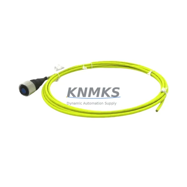
The Bently Nevada CB2W100-125 is a migration-ready interconnect cable engineered for direct replacement and retrofit integration within the Bently Nevada 3500 Series machinery protection and condition monitoring platform. As legacy control infrastructure ages and OEM support windows close, plant engineers and reliability teams face mounting pressure to source verified drop-in replacements that preserve signal integrity, maintain rack compatibility, and eliminate unplanned downtime. The CB2W100-125 addresses each of these challenges with a cable assembly that has been dimensionally and electrically verified against original factory specifications.
When planning a retrofit or spare-parts replenishment for a 3500 Series installation, the CB2W100-125 interconnect cable is typically the first component to be evaluated. It serves as the physical and electrical bridge between the Bently Nevada 3500/15 Power Supply and downstream I/O and communication modules mounted in the same rack. Confirming the correct cable length — in this case 125 cm — is essential before committing to a replacement order, particularly in installations where the power supply and the first I/O module are separated by a full rack width or where cable routing passes through conduit or cable trays with limited slack.
Before installation, engineers should verify terminal block pinout compatibility against the existing wiring diagram. The CB2W100-125 uses the standard Bently Nevada 25-pin D-sub connector format, which mates directly with the backplane interface on 3500/20 Rack Interface Module assemblies. If the existing rack has been modified to accommodate a 3500/22M Transient Data Interface or a 3500/92 Communication Gateway Module, the cable routing path and connector clearance should be re-confirmed prior to final installation. In multi-rack configurations where a 3500/05 System Monitor is present, the interconnect cable must be routed to avoid interference with the system monitor’s front-panel access points.
Firmware compatibility is another critical checkpoint. The 3500 Series rack firmware version governs how the rack interface module interprets signals passed through the interconnect cable. If the replacement is being performed as part of a broader system upgrade — for example, migrating from an older 3500 rack firmware to a version that supports Modbus TCP or EtherNet/IP communication via the 3500/92 Communication Gateway — the cable replacement should be sequenced after the firmware update is confirmed stable. This sequencing prevents a scenario where a new cable is installed into a rack that subsequently requires a full power cycle for firmware flashing, which would necessitate re-termination and re-verification of the cable assembly.
Installation space confirmation is mandatory in dense rack environments. The CB2W100-125 has a bend radius specification that must be respected when routing through the rear of a 19-inch rack enclosure. In installations where the rack is mounted in a control cabinet alongside a Bently Nevada 3500/15 Power Supply and multiple I/O modules, the available cable management space at the rear of the rack can be limited. A pre-installation mockup using the existing cable as a template is recommended to confirm that the replacement cable can be routed without exceeding its minimum bend radius.
All CB2W100-125 units supplied by KNMKS are subject to outgoing functional testing prior to shipment. Each cable assembly is tested for continuity across all 25 conductors, connector seating force, and shield termination integrity. A test report is available upon request. Units are shipped in anti-static packaging with connector caps installed to protect the mating surfaces during transit. Standard lead time from confirmed order to dispatch is 1–3 business days for in-stock units.
Migration Compatibility Table
| Parameter | CB2W100-125 Specification | Retrofit Notes |
|---|---|---|
| Connector Type | 25-pin D-sub (DB25), male/female | Direct mate with 3500/20 Rack Interface Module backplane |
| Cable Length | 125 cm | Confirm rack-to-module distance before ordering |
| Compatible Rack | Bently Nevada 3500 Series (19-inch) | Verify rear-panel cable management clearance |
| Communication Compatibility | Supports Modbus RTU, RS-232, RS-485 signal paths | Compatible with 3500/92 Communication Gateway Module |
| Power Interface | Passive interconnect; no active power conversion | Confirm 3500/15 Power Supply output voltage before installation |
| Installation Requirement | Minimum bend radius: 50 mm | Route away from high-voltage conductors and heat sources |
| Replacement Scope | Drop-in replacement for OEM CB2W100-125 | No firmware changes required for cable replacement alone |
| Commissioning | Continuity test + connector seating verification | Perform loop check after installation; confirm signal at rack front panel |
| Support terms | 12 Months | Covers manufacturing defects; excludes physical damage post-installation |
Retrofit Planning for Existing Automation Systems
A successful retrofit of the CB2W100-125 interconnect cable rarely occurs in isolation. In most 3500 Series installations, the cable replacement is one element of a broader maintenance or upgrade campaign that may also involve the Bently Nevada 3500/15 Power Supply Module, one or more 3500/40M Proximitor/Seismic Monitor I/O modules, and the 3500/20 Rack Interface Module that anchors the rack’s backplane communication architecture. When multiple modules are being replaced simultaneously, the interconnect cable should be the last component installed to avoid connector damage during module insertion and extraction.
In installations where the 3500 rack communicates with a distributed control system (DCS) or safety instrumented system (SIS) via a 3500/92 Communication Gateway Module, the retrofit plan must account for the communication link re-establishment procedure. After the cable is replaced and the rack is powered up, the communication gateway will typically require a re-initialization sequence to re-establish the Modbus TCP or EtherNet/IP session with the host DCS. This procedure should be documented in the site’s management of change (MOC) record and tested during a planned maintenance window rather than during an emergency repair.
For sites that are simultaneously upgrading their HMI infrastructure — for example, migrating from a legacy Wonderware or iFIX HMI to a modern SCADA platform — the CB2W100-125 replacement provides an opportunity to audit the signal tag mapping between the 3500 rack and the HMI. Any changes to module slot assignments or rack addressing that occur during the retrofit must be reflected in the HMI tag database before the system is returned to service. Failure to update the HMI tag database is one of the most common causes of post-retrofit alarm and display anomalies.
Where the retrofit scope includes I/O expansion — for example, adding a 3500/42M Proximitor/Seismic Monitor to monitor additional machine trains — the interconnect cable routing plan must be updated to accommodate the additional module. The CB2W100-125 length of 125 cm is typically sufficient for standard 19-inch rack configurations, but extended rack assemblies or remote I/O enclosures may require a longer cable variant. KNMKS can advise on alternative cable lengths based on the site’s rack layout drawing.
Downtime Control During System Migration
Minimizing downtime during a CB2W100-125 cable replacement requires a structured pre-outage preparation process. Before the maintenance window opens, the site team should complete a full backup of the 3500 rack configuration using the System 1 Evolution software or the rack’s front-panel configuration export function. This backup preserves all channel configurations, alarm setpoints, and communication parameters, ensuring that the rack can be restored to its pre-outage state within minutes if an unexpected issue arises during the cable replacement.
The replacement procedure itself — disconnecting the existing cable, installing the CB2W100-125, and performing a continuity check — typically requires 15 to 30 minutes for a single-rack installation. However, the total maintenance window should account for the rack power-down and power-up sequence, the communication gateway re-initialization, the HMI alarm acknowledgment procedure, and the post-installation loop check. A realistic total outage duration for a single-rack CB2W100-125 replacement, including all pre- and post-installation steps, is 60 to 90 minutes.
To further reduce risk, KNMKS recommends that sites maintain at least one spare CB2W100-125 in their on-site spare parts inventory. Given the cable’s role as a critical interconnect in the 3500 rack architecture, a failure of this component without an available spare could result in an extended unplanned outage while a replacement is sourced and shipped. KNMKS maintains in-stock inventory of the CB2W100-125 and can dispatch same-day for orders confirmed before 14:00 CST.
For sites operating in hazardous area classifications (Zone 1 or Zone 2), the cable replacement procedure must comply with the site’s hot-work and isolation permit requirements. The 3500 rack must be de-energized and isolated before the cable is disconnected, and the isolation must be verified by a second person before work begins. KNMKS can provide a material safety data sheet and installation guidance document upon request to support the site’s permit-to-work process.
Retrofit Support FAQ
Q1: Is the CB2W100-125 a direct drop-in replacement for the original Bently Nevada cable?
Yes. The CB2W100-125 supplied by KNMKS is manufactured to the same dimensional and electrical specifications as the original Bently Nevada component. The connector type, pin assignment, cable length, and shield termination are identical to the OEM part. No modifications to the rack, backplane, or connected modules are required.
Q2: What commissioning steps are required after installing the CB2W100-125?
After installation, perform a full continuity check across all 25 conductors using a calibrated cable tester. Power up the rack and confirm that the rack interface module front-panel status LEDs indicate normal operation. If a communication gateway module is installed, verify that the Modbus or EtherNet/IP session re-establishes within 60 seconds of rack power-up. Perform a loop check on at least two I/O channels to confirm signal integrity through the new cable.
Q3: Does KNMKS provide outgoing test documentation for the CB2W100-125?
Yes. All CB2W100-125 units undergo continuity testing, connector seating verification, and shield integrity testing before dispatch. A test report is available upon request at the time of order. Units are shipped with connector caps installed and in anti-static packaging. The support terms confirmed by quotation cover manufacturing defects identified during installation or normal operation.
Q4: What is the typical lead time and stock availability for the CB2W100-125?
KNMKS maintains in-stock inventory of the CB2W100-125. Standard lead time from confirmed order to dispatch is 1–3 business days. Same-day dispatch is available for orders confirmed before 14:00 CST. For bulk orders or long-term supply agreements, please contact the KNMKS sales team to discuss pricing and delivery scheduling.
© 2026 KNMKS. All rights reserved.
Original Source: https://knmks.com
Contact: admin@knmks.com | +86 18359268345
Product Identification
- Brand / Ecosystem
-
Bently Nevada
Bently Nevada - Model / Series
-
CB2W100-125
3500 Series - Product Family
- Cables & Connectors
- Availability Status
- Available on request after model and quantity confirmation
- Inquiry Type
- B2B RFQ, replacement inquiry and project spare-part request
- Pre-Quote Check
- Exact SKU, brand, series, quantity, nameplate photos and destination country are checked before quotation
System Path
Where this product fits in the KNMKS automation structure.
Specification & Inquiry Focus
- Cable range
- Sensor, servo, network and circular connectors
- Common needs
- Length, pin count, shielding and plug type
- Project support
- Machine wiring and installation kits
Buyer Confirmation
Information KNMKS checks before replying.
- Exact model
- CB2W100-125
- Brand / ecosystem
- Bently Nevada
- Product family
- Cables & Connectors
- Application note
- Replacement, maintenance, project build or spare-part list
- Useful photos
- Nameplate, installed unit, cabinet layout or connector side
- Delivery details
- Quantity, destination country and target schedule
Document Support
Files and notes can be confirmed during quotation.
- Product photos or nameplate confirmation when available
- Packing and delivery notes before quotation confirmation
- Support scope and delivery terms confirmed per inquiry
- Export document coordination for qualified B2B requests
Inquiry Support
- Cable length and connector type confirmation
- Servo, sensor and network cable inquiry
- Accessory kits for installation teams
What to Send Us
- Brand and exact model number: Bently Nevada CB2W100-125
- Quantity and required delivery time
- Application, replacement requirement or nameplate photo
- Destination country and shipping preference
RFQ Preparation
This is a product inquiry page built for RFQ communication.
Fast Model Check
Send this model to KNMKS for confirmation.
Include quantity, destination country and photos if this is a maintenance replacement. The inquiry will be saved with a reference number after submission.
Brand & Compatibility Note
KNMKS displays automation product information for well-known industrial brand ecosystems and compatible replacement references. Brand names are used for product identification and compatibility reference only; final availability and commercial terms are confirmed per quotation.
 Manufacturing
 Machine Tools
 Packaging
 Energy & Power
 PLCs & Controllers
 HMI & Displays
 Servo Systems
 Variable Frequency Drives