
Overview
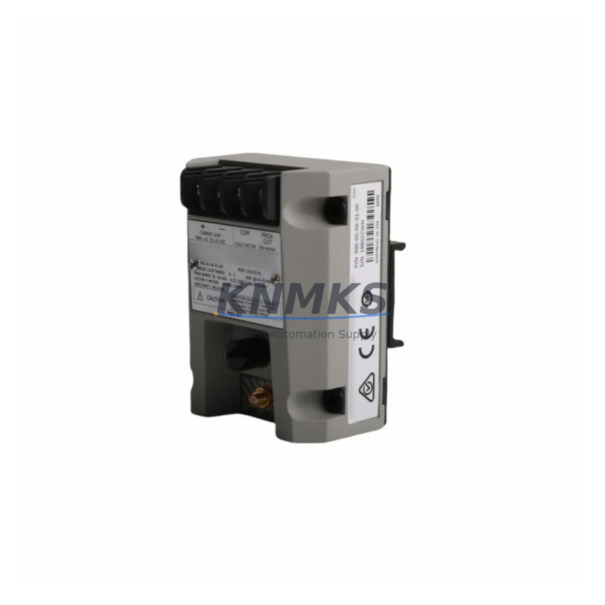
Bently Nevada 990-10-XX-01-05-MOD165353-07 Migration-Ready Vibration Transmitter for Legacy Control Systems
The Bently Nevada 990-10-XX-01-05-MOD165353-07 is a migration-ready vibration transmitter engineered for direct replacement and compatibility upgrade within legacy 990 Series continuous monitoring systems. As industrial facilities face increasing pressure to modernize aging machinery protection infrastructure, this unit provides a validated, drop-in retrofit path that preserves existing wiring, rack architecture, and software logic — dramatically reducing the engineering burden and downtime risk associated with full-system overhauls.
Designed for rotating machinery protection in turbines, compressors, pumps, and motors, the 990-10-XX-01-05-MOD165353-07 delivers 4–20 mA analog output compatible with both legacy DCS platforms and modern SCADA systems. Its signal conditioning circuitry is fully compatible with the Bently Nevada 3500 Series rack infrastructure, allowing engineers to migrate from discontinued 990 Series modules without replacing the entire monitoring backbone. When paired with the 3500/42M Proximitor/Seismic Monitor or the 3500/40M Proximitor/Seismic Monitor, the transmitter integrates seamlessly into existing I/O channel assignments and alarm setpoint configurations.
Before proceeding with installation, retrofit engineers should verify the following critical parameters: terminal block wiring compatibility (the 990 Series uses a 2-wire loop-powered configuration that must be confirmed against the replacement rack’s terminal assignments), available backplane slot addressing, and the firmware revision of the host monitoring rack. In mixed-generation installations where the 3500/20 Rack Interface Module is still in service, address mapping must be re-validated to prevent channel conflicts. Power supply capacity — typically 24 VDC at the rack level — should be audited to confirm headroom for the replacement module’s current draw.
For facilities running Bently Nevada System 1 software, the 990-10-XX-01-05-MOD165353-07 supports direct re-mapping of existing trend and alarm data points, preserving historical vibration baselines and reducing HMI screen reconfiguration time. Engineers migrating from older Keyphasor-based setups should confirm that the 3500/25 Enhanced Keyphasor Module is present in the rack to maintain phase reference signal integrity across the upgraded channel set.
Migration Compatibility Table
| Parameter | Details |
|---|---|
| SKU / Part Number | 990-10-XX-01-05-MOD165353-07 |
| Brand / Series | Bently Nevada / 990 Series |
| Product Type | Vibration Transmitter |
| Output Signal | 4–20 mA analog (loop-powered) |
| Power Supply | 24 VDC (rack-supplied) |
| Mounting / Interface | 990 Series rack backplane; compatible with 3500 Series rack migration |
| Communication Compatibility | Analog 4–20 mA; compatible with Modbus RTU via gateway; System 1 software integration |
| Replacement / Retrofit Path | Direct replacement for discontinued 990 Series vibration transmitter modules |
| Installation Space | Standard 990 Series module form factor; verify rack slot availability before ordering |
| Firmware Compatibility | Compatible with current 3500 Series rack firmware; verify revision with host rack before installation |
| Commissioning Notes | Re-validate channel address, terminal wiring, and alarm setpoints post-installation |
| Support terms | support terms confirmed by quotation — all units tested prior to shipment |
Retrofit Planning for Existing Automation Systems
A successful retrofit begins well before the module arrives on-site. When replacing a discontinued 990 Series vibration transmitter, the first step is a full audit of the control cabinet: confirm that the existing 990 Series rack has available slot capacity, that the backplane bus is undamaged, and that the terminal block wiring harness can be reused without re-termination. In many legacy installations, the wiring was routed for the original 990 Series module pinout, and any deviation in terminal assignment between the old and replacement unit must be documented and corrected before power-up.
Power distribution within the control cabinet is a frequent bottleneck in retrofit projects. The 24 VDC bus feeding the rack must be verified for adequate current capacity, particularly in cabinets where additional I/O expansion — such as adding a 3500/61 Temperature Monitor or a 3500/64 Dynamic Pressure Monitor — has increased the total load since the original system was commissioned. A current audit of the power supply module, often a 3500/15 Power Supply, should be completed before the new transmitter is installed.
Communication protocol migration is another key consideration. Facilities transitioning from hardwired analog loops to networked monitoring architectures may need to introduce a Modbus RTU or PROFIBUS gateway module to bridge the 990 Series analog output to a modern DCS or PLC platform. In these cases, the gateway’s I/O channel mapping must be configured to match the existing System 1 software tag structure to avoid alarm logic disruption. Where Keyphasor phase reference signals are in use, the 3500/25 Enhanced Keyphasor Module must be confirmed as present and correctly addressed in the rack configuration.
HMI screen updates are often underestimated in retrofit planning. If the facility uses a Bently Nevada System 1 operator interface, existing trend displays and alarm banners tied to the old module’s tag names must be remapped to the replacement unit’s channel assignments. This process should be completed and verified in simulation mode before the physical module swap to minimize live system exposure time.
Downtime Control During System Migration
Minimizing unplanned downtime is the primary operational constraint in any machinery protection system retrofit. For the 990-10-XX-01-05-MOD165353-07, the recommended migration sequence begins with a pre-installation bench test: each unit is powered and signal-verified against a calibrated reference source before it enters the plant. This pre-shipment functional test, included as standard with every unit supplied by KNMKS, confirms output linearity, alarm relay operation, and communication integrity before the module reaches the field.
On-site, the swap sequence should be planned to maintain monitoring continuity on adjacent channels. Where the rack architecture permits, the replacement module should be installed in a spare slot first, configured and verified against a live vibration source, and then the original channel re-routed to the new module before the legacy unit is removed. This hot-swap approach — where rack architecture supports it — eliminates the monitoring gap that would otherwise occur during a direct slot-for-slot replacement.
Original PLC or DCS program logic should be backed up and version-controlled before any physical changes are made. In installations where the vibration transmitter feeds a safety interlock or trip circuit, the safety function must be bypassed through the facility’s formal Management of Change process before the module is removed. After installation, a full functional test of the trip circuit — including simulated high-vibration alarm and trip signal verification at the DCS — must be completed before the bypass is lifted and the machine is returned to service.
KNMKS maintains in-stock inventory of the 990-10-XX-01-05-MOD165353-07 and related 990 Series components to support emergency replacement scenarios. Express shipping options are available to minimize the window between module failure and system restoration, and our technical team can provide remote commissioning support to accelerate on-site verification.
Retrofit Support FAQ
Q: Is the 990-10-XX-01-05-MOD165353-07 a direct drop-in replacement for the original 990 Series vibration transmitter?
A: In most installations, yes. The module is designed to match the original 990 Series form factor and terminal wiring configuration. However, engineers should verify the specific terminal block pinout and backplane slot address against the original installation drawings before ordering, as minor hardware revisions across 990 Series production runs may affect wiring compatibility.
Q: What commissioning steps are required after installation?
A: After physical installation, the following steps are required: (1) verify channel address assignment in the rack configuration software, (2) confirm 4–20 mA output calibration against a known vibration reference, (3) test alarm and trip relay outputs at the DCS or safety system, (4) re-validate HMI tag mapping in System 1 or the site SCADA platform, and (5) document the as-installed configuration for the facility’s maintenance records.
Q: Has the unit been tested before shipment?
A: Yes. Every 990-10-XX-01-05-MOD165353-07 supplied by KNMKS undergoes a full functional test prior to shipment, including output signal verification, alarm relay operation, and communication integrity checks. A test report is available upon request.
Q: What support terms and supply continuity can I expect?
A: All units carry a support terms confirmed by quotation covering manufacturing defects and functional failures under normal operating conditions. KNMKS maintains ongoing inventory of the 990-10-XX-01-05-MOD165353-07 and related 990 Series components to support both planned maintenance programs and emergency replacement requirements. Contact admin@knmks.com or +86 18359268345 for current stock availability and lead times.
© 2026 KNMKS. All rights reserved.
Original Source: https://knmks.com
Contact: admin@knmks.com | +86 18359268345
Product Identification
- Brand / Ecosystem
-
Bently Nevada
Bently Nevada - Model / Series
-
990-10-XX-01-05-MOD165353-07
Legacy Control Series - Product Family
- Sensors
- Availability Status
- Available on request after model and quantity confirmation
- Inquiry Type
- B2B RFQ, replacement inquiry and project spare-part request
- Pre-Quote Check
- Exact SKU, brand, series, quantity, nameplate photos and destination country are checked before quotation
System Path
Where this product fits in the KNMKS automation structure.
Specification & Inquiry Focus
- Sensor range
- Photoelectric, proximity and process sensors
- Common needs
- Output type, distance and connector
- Project support
- Machine detection and replacement inquiry
Buyer Confirmation
Information KNMKS checks before replying.
- Exact model
- 990-10-XX-01-05-MOD165353-07
- Brand / ecosystem
- Bently Nevada
- Product family
- Sensors
- Application note
- Replacement, maintenance, project build or spare-part list
- Useful photos
- Nameplate, installed unit, cabinet layout or connector side
- Delivery details
- Quantity, destination country and target schedule
Document Support
Files and notes can be confirmed during quotation.
- Product photos or nameplate confirmation when available
- Packing and delivery notes before quotation confirmation
- Support scope and delivery terms confirmed per inquiry
- Export document coordination for qualified B2B requests
Inquiry Support
- NPN/PNP, analog and digital output checking
- Connector and cable compatibility review
- Fast inquiry support for maintenance teams
What to Send Us
- Brand and exact model number: Bently Nevada 990-10-XX-01-05-MOD165353-07
- Quantity and required delivery time
- Application, replacement requirement or nameplate photo
- Destination country and shipping preference
RFQ Preparation
This is a product inquiry page built for RFQ communication.
Fast Model Check
Send this model to KNMKS for confirmation.
Include quantity, destination country and photos if this is a maintenance replacement. The inquiry will be saved with a reference number after submission.
Brand & Compatibility Note
KNMKS displays automation product information for well-known industrial brand ecosystems and compatible replacement references. Brand names are used for product identification and compatibility reference only; final availability and commercial terms are confirmed per quotation.
 Manufacturing
 Machine Tools
 Packaging
 Energy & Power
 PLCs & Controllers
 HMI & Displays
 Servo Systems
 Variable Frequency Drives