
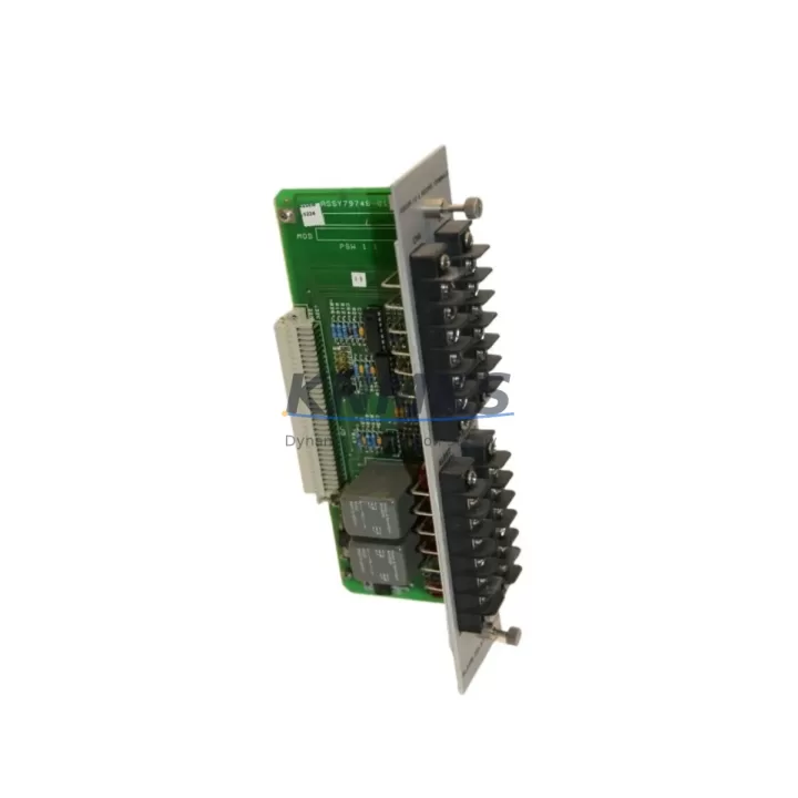
Overview
Bently Nevada 81546-01 Maintenance-Proven Spare Part for Factory Uptime
The Bently Nevada 81546-01 is a Relay Output Module designed for the 3500 Series Machine Protection System (MPS) — one of the most widely deployed vibration monitoring and machinery protection platforms in continuous-process industries including oil & gas, petrochemical, power generation, and heavy manufacturing. Sourced as an original spare, the 81546-01 provides relay-based alarm and trip output capability that is critical to protecting rotating equipment such as turbines, compressors, pumps, and fans from catastrophic failure.
For maintenance engineers managing aging 3500 Series racks, the 81546-01 is a high-priority line item on any annual inspection checklist. Relay output modules are subject to contact wear, coil fatigue, and insulation degradation over extended service cycles — particularly in high-cycle alarm environments. Proactive replacement during planned shutdowns is far less costly than an unplanned trip caused by a failed relay contact during peak production. Stocking at least one verified spare 81546-01 per critical rack is standard practice in facilities operating under ISA-18.2 or IEC 61511 safety instrumentation guidelines.
Procurement engineers sourcing the 81546-01 should verify the module revision level against the installed 3500 rack firmware to ensure seamless drop-in compatibility. The 81546-01 is compatible with 3500/32 Four-Channel Relay Module configurations and integrates directly with the 3500 rack backplane without requiring software reconfiguration in most standard installations. All units are tested prior to shipment and backed by a support terms confirmed by quotation covering manufacturing defects and functional performance.
Spare Maintenance Table
| SKU / Part Number | 81546-01 |
| Brand | Bently Nevada |
| Series | 3500 Series Machine Protection System |
| Module Type | Relay Output Module |
| Relay Configuration | Four-channel relay output, normally energized / de-energized selectable |
| Output Rating | Dry contact relay, rated for alarm and trip circuits |
| Backplane Compatibility | 3500 Series rack backplane (3500/05, 3500/15, 3500/25) |
| Compatible Monitors | 3500/32, 3500/42, 3500/44, 3500/46 series monitors |
| Installation | Direct rack insertion, no tools required; hot-swap capable in supported configurations |
| Operating Environment | Industrial control cabinet; ambient 0–65°C, non-condensing |
| Origin | United States |
| Condition | Original spare, pre-shipment tested |
| Support terms | 12 months from date of shipment |
| Lead Time | In-stock; ships within 1–3 business days |
Maintenance Planning for Continuous Operation
When replacing the 81546-01 Relay Output Module during a scheduled outage or emergency intervention, a thorough inspection of the surrounding 3500 rack components is essential to prevent repeat failures and ensure system integrity. Maintenance teams should treat the relay module replacement as an opportunity to audit the full protection loop.
Begin with the 3500/05 Power Supply Module — relay output modules are sensitive to supply voltage ripple and transient spikes. A degraded power supply can accelerate relay coil wear and cause intermittent trip outputs. Verify output voltage stability under load before reinstalling the 81546-01. If the rack uses a redundant power configuration, test both supply channels independently.
Next, inspect the 3500 rack backplane connector pins and edge contacts. Oxidized or bent backplane pins are a common root cause of relay module communication faults that are misdiagnosed as module failures. Clean contacts with approved contact cleaner and verify seating torque on all adjacent modules.
For facilities using the 3500/32 Four-Channel Relay Module in parallel with the 81546-01 for redundant trip output, confirm that both modules are on the same firmware revision and that the relay voting logic (1oo2, 2oo3) is correctly configured in the 3500 System Configuration Utility. Mismatched firmware between relay modules is a known source of nuisance trips during startup.
Wiring terminations at the 3500 I/O terminal blocks should be re-torqued to specification during any relay module replacement. Loose terminals in high-vibration environments are a leading cause of intermittent alarm signals that can mask genuine machinery faults. Use calibrated torque screwdrivers and document terminal resistance readings as part of the maintenance record.
If the 3500 rack communicates with a DCS or safety PLC via Modbus or Ethernet/IP, verify that the relay output status registers are correctly mapped after module replacement. Some 3500 configurations require a communication module reset (e.g., 3500/92 Communication Gateway Module) to re-establish correct register addressing following a hot-swap event.
Finally, review the condition of any signal isolators or surge protection devices installed on the relay output wiring to field devices (solenoid valves, shutdown actuators, annunciator panels). These components absorb transient energy from inductive loads and should be replaced on a 3–5 year cycle regardless of apparent condition. Stocking spares of the 81546-01 alongside compatible signal isolators and terminal block fuse inserts ensures that your team can complete a full loop restoration without waiting on additional procurement.
Site Replacement Workflow
Step 1 — Pre-Replacement Verification: Confirm the replacement 81546-01 part number and revision match the installed module. Cross-reference the 3500 rack configuration report (exported from System Configuration Utility) to verify slot assignment and relay voting parameters.
Step 2 — Safety Isolation: Coordinate with the control room to place the affected machinery protection channel in bypass mode per site MOC (Management of Change) procedure. Do not remove the relay module while the protection channel is active in a live trip circuit without authorization.
Step 3 — Module Removal: Loosen the module retaining screws, disconnect the I/O terminal block, and slide the 81546-01 out of the rack slot. Inspect the ejected module for visible damage — burnt contacts, discolored PCB areas, or swollen components — and document findings for the maintenance record.
Step 4 — Installation: Insert the replacement 81546-01 into the rack slot, reconnect the I/O terminal block, and tighten retaining screws to specification. The module will self-initialize within the 3500 rack; observe the front-panel LED sequence to confirm successful initialization (typically: red → amber → green).
Step 5 — Functional Test: From the System Configuration Utility, perform a relay output function test to verify each relay channel operates correctly. Confirm alarm and trip setpoints are correctly loaded from the rack configuration. Re-torque all terminal connections and restore the protection channel from bypass.
Step 6 — Documentation: Record the replacement in the equipment maintenance log, including the old module serial number, new module serial number, date, technician ID, and post-replacement test results. Update the spare parts inventory to trigger reorder of a replacement 81546-01 for the next event.
Spare Parts Support FAQ
Q1: Is the 81546-01 compatible with all 3500 Series rack configurations?
The 81546-01 is designed for the 3500 Series MPS platform and is compatible with standard 3500 rack backplanes. Compatibility with specific monitor modules (3500/32, 3500/42, 3500/44, 3500/46) should be confirmed against the installed rack configuration report. Revision-level matching is recommended for racks running older firmware versions. Contact our technical team with your rack serial number for a compatibility confirmation before ordering.
Q2: What is included in the support terms confirmed by quotation?
All 81546-01 units are covered by a support terms confirmed by quotation from the date of shipment. The support terms covers manufacturing defects and functional performance failures under normal operating conditions. Each unit undergoes pre-shipment functional testing. Support requests are processed with priority turnaround to minimize your downtime exposure.
Q3: How quickly can the 81546-01 be shipped, and what documentation is provided?
In-stock units ship within 1–3 business days. Each shipment includes a packing list, test report, and support terms certificate. Export documentation (commercial invoice, packing declaration) is provided for international orders. Expedited shipping options are available for emergency downtime situations — contact admin@knmks.com with your urgency level.
Q4: Can you support long-term supply of the 81546-01 for multi-year maintenance contracts?
Yes. We maintain ongoing inventory of the 81546-01 and can support blanket purchase orders, annual supply agreements, and scheduled delivery programs for facilities managing large 3500 Series installed bases. Long-term supply agreements include price stability commitments and priority allocation during periods of market shortage — a critical consideration for legacy Bently Nevada components with extended lead times from OEM channels.
—
© 2026 KNMKS. All rights reserved.
Original Source: https://knmks.com
Contact: admin@knmks.com | +86 18359268345
Product Identification
- Brand / Ecosystem
-
Bently Nevada
Bently Nevada - Model / Series
-
81546-01
3500 Series - Product Family
- PLCs & Controllers
- Availability Status
- Available on request after model and quantity confirmation
- Inquiry Type
- B2B RFQ, replacement inquiry and project spare-part request
- Pre-Quote Check
- Exact SKU, brand, series, quantity, nameplate photos and destination country are checked before quotation
System Path
Where this product fits in the KNMKS automation structure.
Specification & Inquiry Focus
- Control platform
- PLC, PAC and modular controllers
- Common needs
- CPU, rack, power and I/O expansion
- Project support
- Replacement, cabinet build and maintenance
Buyer Confirmation
Information KNMKS checks before replying.
- Exact model
- 81546-01
- Brand / ecosystem
- Bently Nevada
- Product family
- PLCs & Controllers
- Application note
- Replacement, maintenance, project build or spare-part list
- Useful photos
- Nameplate, installed unit, cabinet layout or connector side
- Delivery details
- Quantity, destination country and target schedule
Document Support
Files and notes can be confirmed during quotation.
- Product photos or nameplate confirmation when available
- Packing and delivery notes before quotation confirmation
- Support scope and delivery terms confirmed per inquiry
- Export document coordination for qualified B2B requests
Inquiry Support
- Model cross-checking before quotation
- CPU, power, rack and expansion module matching
- Support for replacement and project inquiry
What to Send Us
- Brand and exact model number: Bently Nevada 81546-01
- Quantity and required delivery time
- Application, replacement requirement or nameplate photo
- Destination country and shipping preference
RFQ Preparation
This is a product inquiry page built for RFQ communication.
Fast Model Check
Send this model to KNMKS for confirmation.
Include quantity, destination country and photos if this is a maintenance replacement. The inquiry will be saved with a reference number after submission.
Brand & Compatibility Note
KNMKS displays automation product information for well-known industrial brand ecosystems and compatible replacement references. Brand names are used for product identification and compatibility reference only; final availability and commercial terms are confirmed per quotation.
 Manufacturing
 Machine Tools
 Packaging
 Energy & Power
 HMI & Displays
 Servo Systems
 Variable Frequency Drives
 Sensors