
Overview
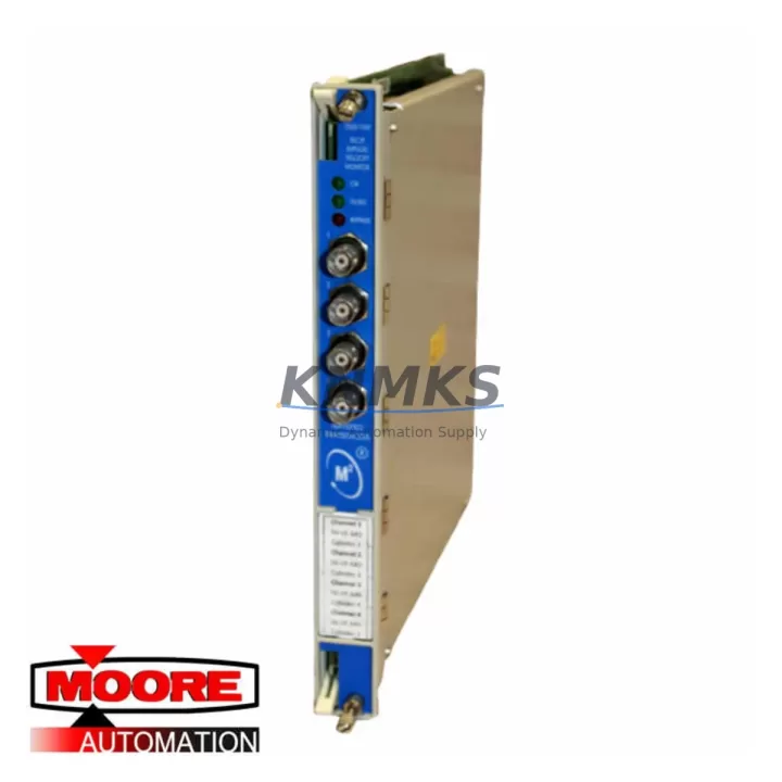
Bently Nevada 3500/70M 140734-09 Migration-Ready Velocity Monitor for Legacy Control Systems
The Bently Nevada 3500/70M 140734-09 is a migration-ready velocity monitor module engineered for direct integration into the Bently Nevada 3500 Series machinery protection system. Designed to replace discontinued or end-of-life velocity monitoring hardware, this module supports plant engineers and maintenance teams executing legacy control system upgrades, control cabinet retrofits, and long-term spare parts lifecycle planning. With pre-shipment functional testing, verified compatibility across the 3500 rack architecture, and a support terms confirmed by quotation, the 3500/70M 140734-09 is a reliable solution for facilities managing aging rotating machinery protection infrastructure.
The 3500/70M accepts velocity transducer inputs and provides continuous vibration monitoring for turbines, compressors, pumps, and other critical rotating assets. Its dual-channel architecture and configurable alert/danger setpoints make it suitable for both direct replacement of failed modules and planned system upgrades where the original 3500/70 or 3500/70M variants are no longer available through OEM channels. Engineers migrating from older 3500 rack configurations will find the module’s backplane connector pinout and power draw consistent with standard 3500 Series slot assignments, minimizing rewiring requirements during retrofit.
Migration Compatibility Table
| Parameter | Details |
|---|---|
| SKU / Part Number | 3500/70M 140734-09 |
| Series | Bently Nevada 3500 Series |
| Module Function | Dual-Channel Velocity Monitor |
| Replaces / Supersedes | 3500/70, earlier 3500/70M variants |
| Backplane Interface | 3500 Series standard rack backplane (compatible with 3500/05, 3500/15, 3500/20 racks) |
| Input Type | Velocity transducer (seismic / velocity sensor) |
| Communication | Rack-based Modbus / System 1 integration via 3500/92 or 3500/93 communication gateway |
| Power Requirement | Supplied via 3500 rack power module (3500/15 or 3500/20 PSU) |
| Installation Space | Single slot, standard 3500 Series rack |
| Firmware Compatibility | Compatible with 3500 Rack Configuration Software (RCS); verify RCS version prior to deployment |
| Retrofit Recommendation | Direct slot replacement; confirm channel configuration and setpoints in RCS before restart |
| Commissioning Notes | Reconfigure alert/danger setpoints; verify transducer wiring polarity and cable shielding |
| Support terms | 12 Months from shipment date |
| Pre-Shipment Testing | Full functional test performed on every unit prior to dispatch |
Retrofit Planning for Existing Automation Systems
Successful integration of the 3500/70M 140734-09 into an existing machinery protection system requires a structured retrofit plan that accounts for rack architecture, power budget, and signal chain integrity. Before removing the failed or obsolete module, maintenance teams should document the current channel configuration using the 3500 Rack Configuration Software, capturing all alert and danger setpoints, transducer scale factors, and OK relay logic. This configuration file serves as the baseline for post-replacement commissioning and significantly reduces the risk of setpoint errors during restart.
Power capacity verification is a critical pre-installation step. The 3500/15 or 3500/20 power supply module must have sufficient headroom to support the 3500/70M 140734-09 alongside other installed modules such as the 3500/40M proximitor monitor, 3500/42M proximitor/seismic monitor, or 3500/45 position monitor. In high-density rack configurations where multiple I/O and monitor modules share a single PSU, a power audit should be completed before adding or replacing modules to avoid nuisance trips or PSU overload conditions.
Terminal wiring for velocity transducer inputs should be inspected during the retrofit. Confirm that cable shielding is intact and that shield grounding follows the Bently Nevada single-point grounding convention to prevent ground loop interference. If the installation involves long cable runs from the transducer to the rack, verify that the cable capacitance remains within the 3500/70M input specification. In facilities where the 3500 rack communicates with a DCS or historian via the 3500/92 Ethernet communication module or 3500/93 serial communication module, confirm that the module address assignments in the rack remain unchanged after the slot replacement to avoid communication mapping errors in the host system.
For plants running Bently Nevada System 1 condition monitoring software, the replacement module should be re-registered in the System 1 database after installation. Channel tags, engineering units, and alarm thresholds configured in System 1 must be verified against the physical module configuration to ensure data integrity in the historian and alarm management system. HMI displays referencing velocity channel data should also be reviewed to confirm that tag bindings remain valid after the module swap.
Downtime Control During System Migration
Minimizing unplanned downtime during a 3500/70M 140734-09 replacement requires preparation that begins well before the maintenance window. The most effective approach is to pre-configure the replacement module offline using the 3500 Rack Configuration Software before the scheduled outage. By loading the saved rack configuration file onto the new module in a bench environment, the installation team can verify setpoints, OK relay logic, and channel assignments without consuming time during the live maintenance window.
During the physical swap, the original program logic in the 3500 rack is preserved in the rack’s non-volatile memory and is not affected by a single-module replacement. However, the replacement module itself must be individually configured, as module-level parameters are stored on the module rather than the rack backplane. Teams should plan for a post-installation functional check that includes transducer signal verification, OK relay status confirmation, and a review of alert and danger output relay states before returning the machine to service.
For facilities where continuous monitoring is required during the replacement, consider whether a temporary bypass or inhibit function can be applied to the affected channels through the 3500 rack’s inhibit logic. This allows the machine to remain in operation while the module is replaced, with monitoring restored immediately after the new 3500/70M 140734-09 is installed and configured. Coordinating the replacement with the control room operator ensures that any transient alarm conditions generated during the module swap are acknowledged and documented rather than triggering an unplanned shutdown.
Stocking a verified replacement unit of the 3500/70M 140734-09 as a critical spare reduces mean time to repair (MTTR) for velocity monitoring failures. Given the end-of-life status of many 3500 Series modules through OEM channels, maintaining at least one pre-tested spare in the plant’s critical spare inventory is a recognized best practice for facilities operating legacy Bently Nevada machinery protection systems.
Retrofit Support FAQ
Q: Is the 3500/70M 140734-09 a direct replacement for the original 3500/70M?
A: Yes. The 140734-09 is a compatible replacement for earlier 3500/70M variants and occupies the same single rack slot. Terminal wiring connections and backplane interface are consistent with the standard 3500 Series architecture. Setpoints and channel configuration must be re-entered using the 3500 Rack Configuration Software after installation.
Q: What commissioning steps are required after installing the replacement module?
A: After physical installation, connect the 3500 Rack Configuration Software to the rack and load the saved configuration file for the affected slot. Verify all alert and danger setpoints, transducer scale factors, and OK relay logic. Perform a transducer signal check to confirm live velocity readings are within expected range before releasing the machine to normal operation.
Q: How do I confirm wiring compatibility before installation?
A: Review the terminal block wiring diagram for the existing 3500/70M installation against the 3500/70M 140734-09 terminal assignment documentation. Velocity transducer input terminals, shield ground connections, and relay output wiring should be verified point-by-point. If the existing cable labels are unclear, use a continuity tester to confirm each connection before powering the rack.
Q: What support terms and testing are included with this module?
A: Every 3500/70M 140734-09 unit undergoes full functional pre-shipment testing prior to dispatch. A support terms confirmed by quotation is provided from the shipment date, covering manufacturing defects and functional failures under normal operating conditions. Expedited shipping options are available for emergency replacement requirements.
© 2026 KNMKS. All rights reserved.
Original Source: https://knmks.com
Contact: admin@knmks.com | +86 18359268345
Product Identification
- Brand / Ecosystem
-
Bently Nevada
Bently Nevada - Model / Series
-
3500/70M 140734-09
3500 Series - Product Family
- PLCs & Controllers
- Availability Status
- Available on request after model and quantity confirmation
- Inquiry Type
- B2B RFQ, replacement inquiry and project spare-part request
- Pre-Quote Check
- Exact SKU, brand, series, quantity, nameplate photos and destination country are checked before quotation
System Path
Where this product fits in the KNMKS automation structure.
Specification & Inquiry Focus
- Control platform
- PLC, PAC and modular controllers
- Common needs
- CPU, rack, power and I/O expansion
- Project support
- Replacement, cabinet build and maintenance
Buyer Confirmation
Information KNMKS checks before replying.
- Exact model
- 3500/70M 140734-09
- Brand / ecosystem
- Bently Nevada
- Product family
- PLCs & Controllers
- Application note
- Replacement, maintenance, project build or spare-part list
- Useful photos
- Nameplate, installed unit, cabinet layout or connector side
- Delivery details
- Quantity, destination country and target schedule
Document Support
Files and notes can be confirmed during quotation.
- Product photos or nameplate confirmation when available
- Packing and delivery notes before quotation confirmation
- Support scope and delivery terms confirmed per inquiry
- Export document coordination for qualified B2B requests
Inquiry Support
- Model cross-checking before quotation
- CPU, power, rack and expansion module matching
- Support for replacement and project inquiry
What to Send Us
- Brand and exact model number: Bently Nevada 3500/70M 140734-09
- Quantity and required delivery time
- Application, replacement requirement or nameplate photo
- Destination country and shipping preference
RFQ Preparation
This is a product inquiry page built for RFQ communication.
Fast Model Check
Send this model to KNMKS for confirmation.
Include quantity, destination country and photos if this is a maintenance replacement. The inquiry will be saved with a reference number after submission.
Brand & Compatibility Note
KNMKS displays automation product information for well-known industrial brand ecosystems and compatible replacement references. Brand names are used for product identification and compatibility reference only; final availability and commercial terms are confirmed per quotation.
 Manufacturing
 Machine Tools
 Packaging
 Energy & Power
 HMI & Displays
 Servo Systems
 Variable Frequency Drives
 Sensors