
Overview
Bently Nevada 3500/50-01-00-01 Migration-Ready Tachometer Module: Legacy Control System Upgrade & Retrofit
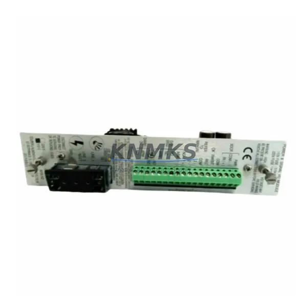
The Bently Nevada 3500/50-01-00-01 is a migration-ready tachometer module engineered for direct integration into the 3500 Series machinery protection system. As legacy rotating machinery monitoring platforms approach end-of-life, maintenance engineers and reliability teams face increasing pressure to source verified replacement modules that preserve existing rack architecture, wiring infrastructure, and system logic without triggering a full platform overhaul. The 3500/50-01-00-01 addresses this challenge by delivering drop-in compatibility with the 3500 Series backplane, retaining the original terminal block pinout and supporting the same speed and overspeed detection functions as the discontinued predecessor modules.
When planning a retrofit around the 3500/50-01-00-01, engineers must confirm several critical parameters before installation. Power supply capacity within the 3500 rack — typically provided by a 3500/15 Power Supply module — must be verified against the aggregate draw of all installed I/O and processing modules. Terminal wiring from the field-mounted proximity probes or magnetic pickups must be mapped against the module’s input channel configuration, confirming signal type (active or passive), voltage range, and cable shielding continuity. The backplane slot assignment must match the module address configured in the 3500 rack’s system software, as address conflicts will prevent the module from initializing correctly during power-up.
Program compatibility is a key concern during any tachometer module swap. The 3500 Series system software retains channel configuration, alarm setpoints, and trip multiplier settings in non-volatile memory within the 3500/20 Rack Interface Module. Before removing the legacy tachometer module, engineers should export the full rack configuration file and verify that the replacement 3500/50-01-00-01 accepts the same firmware revision. If the installed rack is running an older firmware baseline, a controlled firmware update on the 3500/20 may be required before the new module will be recognized. This step is critical to avoid configuration mismatch alarms during commissioning.
HMI screen updates are often overlooked during tachometer module replacements. If the plant DCS or SCADA system — such as a Honeywell Experion PKS or Emerson DeltaV node — is receiving speed and overspeed status via a 3500/92 Communication Gateway Module using Modbus TCP or OPC DA, the tag mapping must be validated after module swap to confirm that speed channel data is still being transmitted on the correct register addresses. Any change in module slot position within the rack will shift the Modbus register map and require corresponding updates in the DCS historian and alarm management system.
Installation space within the control cabinet should be confirmed before ordering. The 3500/50-01-00-01 occupies a standard single-slot position in the 3500 Series rack and does not require additional mounting hardware beyond the existing rack guides. However, if the retrofit is being performed as part of a broader control cabinet upgrade — for example, alongside replacement of a 3500/32 4-Channel Relay Module or a 3500/42M Proximitor/Seismic Monitor Module — the total rack slot count must be re-evaluated to ensure no slot conflicts arise from the expanded module set.
Field commissioning of the 3500/50-01-00-01 involves verifying speed signal acquisition from the proximity probe or magnetic pickup, confirming that the module’s LED status indicators show normal operation, and running a simulated overspeed test to validate the trip relay output. All commissioning steps should be documented and cross-referenced against the original system acceptance test records to support audit and compliance requirements in regulated industries such as oil and gas, petrochemical, and power generation.
Migration Compatibility Table
| Parameter | Details |
|---|---|
| SKU / Part Number | 3500/50-01-00-01 |
| Brand / Series | Bently Nevada / 3500 Series |
| Module Type | Tachometer Module (Speed & Overspeed Detection) |
| Rack Compatibility | 3500 Series Rack (Standard Backplane, Single Slot) |
| Input Signal Type | Proximity Probe / Magnetic Pickup (Active & Passive) |
| Communication Interface | Via 3500/92 Gateway (Modbus TCP / OPC DA) |
| Terminal Wiring | Compatible with original 3500/50 terminal block pinout |
| Firmware Compatibility | Verify rack firmware via 3500/20 Rack Interface Module before swap |
| Replacement Recommendation | Direct drop-in for legacy 3500/50 tachometer variants |
| Commissioning Requirement | Simulated overspeed test + DCS tag map validation required |
| Support terms | support terms confirmed by quotation — Tested & Verified Before Shipment |
Retrofit Planning for Existing Automation Systems
A successful retrofit centered on the 3500/50-01-00-01 typically involves coordinating several interdependent components within the same rack or control cabinet. The 3500/15 Power Supply module must be confirmed as capable of sustaining the full rack load after the tachometer module is installed, particularly if the retrofit is being performed alongside other module additions. Engineers sourcing the 3500/50-01-00-01 as a replacement for a failed or discontinued tachometer module should simultaneously audit the condition of the 3500/20 Rack Interface Module, which manages system-level communication and configuration storage for the entire rack.
In systems where the tachometer module feeds overspeed trip signals to a relay output card, the 3500/32 4-Channel Relay Module wiring must be inspected to confirm that trip relay assignments remain consistent after the module swap. If the plant is also upgrading its vibration monitoring capability, the 3500/42M Proximitor/Seismic Monitor Module may be installed in adjacent slots, and its channel addressing must be verified to avoid conflicts with the tachometer module’s slot assignment.
For plants integrating the 3500 rack into a broader SCADA or DCS environment, the 3500/92 Communication Gateway Module serves as the critical link between the machinery protection system and the plant network. Any changes to module slot positions during the retrofit will require a corresponding update to the gateway’s Modbus register map configuration. Signal isolators installed between the proximity probe field cables and the rack input terminals should also be inspected during the retrofit to confirm that signal conditioning remains within the module’s specified input range.
Downtime Control During System Migration
Minimizing unplanned downtime during a tachometer module replacement requires a structured pre-outage preparation process. Before the maintenance window opens, the full 3500 rack configuration should be exported and archived, including all channel setpoints, alarm thresholds, trip multipliers, and communication gateway register maps. A pre-tested replacement 3500/50-01-00-01 module — confirmed to be running a compatible firmware revision — should be staged at the work site with all required tools and terminal documentation.
During the swap, the original module should be removed only after confirming that the machinery is in a safe, de-energized state and that all field wiring labels are documented. The replacement module should be inserted into the same rack slot, and the system should be powered up in a controlled sequence to allow the 3500/20 Rack Interface Module to recognize and initialize the new tachometer module before any alarm or trip functions are re-enabled.
Post-installation, a simulated speed signal test should be performed to confirm that the module is acquiring data correctly and that the overspeed trip relay is responding at the configured setpoint. DCS and SCADA tag values should be cross-checked against the pre-outage baseline to confirm that no register mapping errors were introduced during the swap. With proper preparation, a 3500/50-01-00-01 module replacement can typically be completed within a planned maintenance window of two to four hours, preserving control system continuity and minimizing production impact.
Retrofit Support FAQ
Q1: Is the 3500/50-01-00-01 a direct replacement for earlier 3500/50 tachometer module variants?
A: Yes. The 3500/50-01-00-01 is designed as a drop-in replacement for legacy 3500/50 tachometer module variants within the 3500 Series rack. Terminal block pinout, slot dimensions, and backplane interface are compatible with the original rack architecture. Firmware version compatibility should be confirmed via the 3500/20 Rack Interface Module before installation.
Q2: What commissioning steps are required after installing the 3500/50-01-00-01?
A: After installation, engineers should perform a simulated speed signal test to confirm channel acquisition, verify that the module’s status LEDs indicate normal operation, and run a simulated overspeed test to validate the trip relay output. DCS and SCADA tag mapping should be cross-checked to confirm that Modbus register addresses remain consistent with the pre-swap configuration.
Q3: How is the module tested before shipment, and what support terms is provided?
A: Each 3500/50-01-00-01 unit is functionally tested before shipment to verify speed signal acquisition, overspeed trip relay response, and communication interface operation. All units are supplied with a support terms confirmed by quotation covering manufacturing defects and functional failures under normal operating conditions.
Q4: What is the typical lead time and stock availability for the 3500/50-01-00-01?
A: KNMKS maintains regional inventory of the 3500/50-01-00-01 to support urgent replacement requirements. Standard lead time for in-stock units is 3–7 business days for international shipments. For critical plant shutdowns or emergency replacement requirements, expedited shipping options are available. Contact admin@knmks.com or +86 18359268345 to confirm current stock availability.
© 2026 KNMKS. All rights reserved.
Original Source: https://knmks.com
Contact: admin@knmks.com | +86 18359268345
Product Identification
- Brand / Ecosystem
-
Bently Nevada
Bently Nevada - Model / Series
-
3500/50-01-00-01
3500 Series - Product Family
- PLCs & Controllers
- Availability Status
- Available on request after model and quantity confirmation
- Inquiry Type
- B2B RFQ, replacement inquiry and project spare-part request
- Pre-Quote Check
- Exact SKU, brand, series, quantity, nameplate photos and destination country are checked before quotation
System Path
Where this product fits in the KNMKS automation structure.
Specification & Inquiry Focus
- Control platform
- PLC, PAC and modular controllers
- Common needs
- CPU, rack, power and I/O expansion
- Project support
- Replacement, cabinet build and maintenance
Buyer Confirmation
Information KNMKS checks before replying.
- Exact model
- 3500/50-01-00-01
- Brand / ecosystem
- Bently Nevada
- Product family
- PLCs & Controllers
- Application note
- Replacement, maintenance, project build or spare-part list
- Useful photos
- Nameplate, installed unit, cabinet layout or connector side
- Delivery details
- Quantity, destination country and target schedule
Document Support
Files and notes can be confirmed during quotation.
- Product photos or nameplate confirmation when available
- Packing and delivery notes before quotation confirmation
- Support scope and delivery terms confirmed per inquiry
- Export document coordination for qualified B2B requests
Inquiry Support
- Model cross-checking before quotation
- CPU, power, rack and expansion module matching
- Support for replacement and project inquiry
What to Send Us
- Brand and exact model number: Bently Nevada 3500/50-01-00-01
- Quantity and required delivery time
- Application, replacement requirement or nameplate photo
- Destination country and shipping preference
RFQ Preparation
This is a product inquiry page built for RFQ communication.
Fast Model Check
Send this model to KNMKS for confirmation.
Include quantity, destination country and photos if this is a maintenance replacement. The inquiry will be saved with a reference number after submission.
Brand & Compatibility Note
KNMKS displays automation product information for well-known industrial brand ecosystems and compatible replacement references. Brand names are used for product identification and compatibility reference only; final availability and commercial terms are confirmed per quotation.
 Manufacturing
 Machine Tools
 Packaging
 Energy & Power
 HMI & Displays
 Servo Systems
 Variable Frequency Drives
 Sensors