
Overview
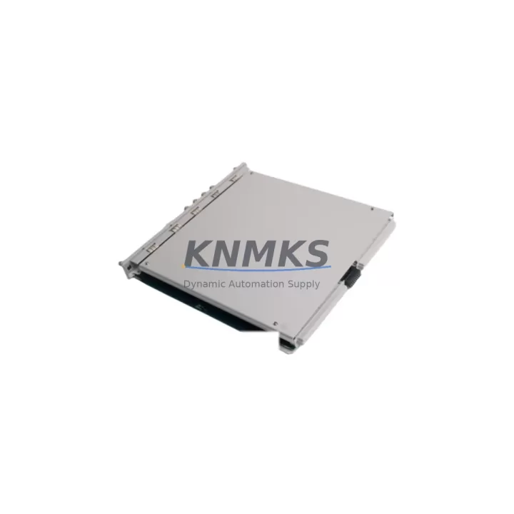
Bently Nevada 3500/33M Migration-Ready Relay Output Module: Legacy System Retrofit & Compatibility Upgrade
The Bently Nevada 3500/33M is a 16-channel relay output module engineered for the 3500 Series machinery protection system (MPS) platform. As legacy 3500 Series installations approach end-of-support milestones and original relay output modules become increasingly difficult to source, the 3500/33M serves as the authoritative migration-ready replacement — preserving existing rack architecture, terminal wiring, and system logic without requiring a full platform overhaul. This module is fully tested prior to shipment, backed by a support terms confirmed by quotation, and available from in-region stock to minimize lead-time risk during critical maintenance windows.
For maintenance engineers managing aging turbine protection panels, compressor monitoring cabinets, or rotating equipment control systems, the 3500/33M provides a direct, back-to-back compatible relay output solution. It slots into the standard 3500 Series 19-inch rack alongside modules such as the 3500/15 Power Supply, 3500/20 Rack Interface Module (RIM), and 3500/22M Transient Data Interface, preserving the existing backplane communication architecture and eliminating the need to re-engineer the rack layout or modify the control cabinet footprint.
Migration Compatibility Table
| Parameter | Detail |
|---|---|
| Replaced / Legacy Module | Bently Nevada 3500/33 (original relay output), discontinued relay output variants |
| Platform Compatibility | Bently Nevada 3500 Series Machinery Protection System |
| Relay Output Channels | 16 relay output channels |
| Rack / Backplane Interface | Standard 3500 Series backplane; compatible with 3500/05 and 3500/05-01-02-00-00 rack assemblies |
| Terminal Wiring Compatibility | Retains existing I/O terminal block wiring; no field rewiring required in standard retrofit scenarios |
| Communication Protocol | Rack-internal backplane bus; compatible with 3500/20 RIM for Modbus, Ethernet/IP, and OPC-DA integration |
| Power Supply Requirement | Supplied via 3500 Series rack backplane from 3500/15 Power Supply module |
| Installation Space | Single-slot 3500 Series module form factor; confirm available slot position in existing rack |
| Firmware / Configuration | Configured via System 1 or Rack Configuration Software; verify firmware version compatibility before deployment |
| Commissioning Requirement | Relay setpoint verification, trip logic confirmation, and functional relay test required post-installation |
| Support terms | support terms confirmed by quotation — all units tested prior to shipment |
Retrofit Planning for Existing Automation Systems
A successful 3500/33M retrofit begins with a thorough audit of the existing 3500 Series rack configuration. Before removing the legacy relay output module, engineers should document the current slot assignment, relay channel-to-trip-function mapping, and the wiring schedule for each of the 16 output channels. In most installations, the relay outputs are wired to solenoid valves, shutdown contactors, or annunciator panels — all of which must remain operational throughout the changeover window.
Power capacity is a critical pre-check item. The 3500/15 Power Supply module must be confirmed to have sufficient headroom to support the 3500/33M alongside other installed modules such as the 3500/40M Proximitor/Seismic Monitor or the 3500/42M Proximitor/Seismic Monitor. If the rack is operating near its power budget, a power supply audit should be completed before the replacement module is installed.
For sites integrating the 3500 Series with a DCS or SCADA platform via the 3500/20 Rack Interface Module, the relay output channel assignments and alarm/trip setpoints stored in the rack configuration must be exported and preserved before the swap. After installing the 3500/33M, the configuration file is re-imported and verified against the original setpoint schedule. Any changes to relay logic — such as latching vs. non-latching behavior or energize-to-trip vs. de-energize-to-trip wiring — must be confirmed against the original functional specification before the system is returned to service.
Sites running System 1 Evolution software for condition monitoring should also verify that the relay output channel tags and alarm group assignments remain intact after the module swap. In some configurations, the 3500/22M Transient Data Interface is used in parallel to capture waveform data during the commissioning test — this provides a useful baseline for confirming that the new relay output module is responding correctly to simulated trip conditions before the machine is restarted.
For control cabinets with limited physical space, confirm that the 3500/33M can be inserted and secured without disturbing adjacent modules or cable harnesses. The standard 3500 Series single-slot form factor is consistent across the relay output module family, but cable dress and terminal block clearance should be verified on-site before the maintenance window begins.
Downtime Control During System Migration
Minimizing unplanned downtime during a relay output module replacement requires a structured pre-outage preparation protocol. The following approach is recommended for 3500/33M installations in live production environments:
Pre-Outage Preparation: Export the full rack configuration from the Rack Configuration Software and store a verified backup. Document all relay channel assignments, setpoints, and trip logic states. Confirm that the replacement 3500/33M has been bench-tested and that the firmware version is compatible with the existing rack software revision. Prepare a functional test checklist covering all 16 relay output channels.
During the Maintenance Window: Place the affected machine train in a safe, controlled shutdown state before removing the legacy module. Insert the 3500/33M into the correct rack slot and secure the module latch. Re-import the saved rack configuration and verify that all relay channel assignments, setpoints, and trip logic states are correctly restored. Do not return the system to automatic protection mode until all relay outputs have been individually tested against their respective trip functions.
Post-Installation Verification: Perform a live relay functional test by simulating trip conditions through the rack configuration software or via the System 1 interface. Confirm that each relay output actuates the correct field device — solenoid valve, shutdown contactor, or annunciator — and that the response time is within the specified trip delay tolerance. Log all test results and retain them as part of the maintenance record for the next scheduled inspection.
By following this structured approach, most 3500/33M relay output module replacements can be completed within a single planned maintenance window, with the machine train returned to full automatic protection within the same shift.
Retrofit Support FAQ
Q1: Is the 3500/33M a direct drop-in replacement for the original 3500/33 relay output module?
In the majority of 3500 Series rack configurations, the 3500/33M is a direct slot-compatible replacement for the original 3500/33. The backplane interface, terminal block wiring, and rack communication architecture are preserved. However, engineers should verify the relay output channel count, trip logic configuration, and firmware version compatibility before installation, as minor differences in relay behavior (latching, energize-to-trip) may require setpoint adjustments in the rack configuration software.
Q2: What commissioning steps are required after installing the 3500/33M?
After physical installation, re-import the saved rack configuration file and verify all 16 relay channel assignments and setpoints. Perform a functional relay test for each output channel by simulating trip conditions through the Rack Configuration Software or System 1 interface. Confirm that each relay actuates the correct field device and that trip response times are within specification. Document all test results before returning the system to automatic protection mode.
Q3: Can the 3500/33M operate in a rack that uses the 3500/20 RIM for Modbus or Ethernet/IP communication?
Yes. The 3500/33M communicates via the standard 3500 Series backplane bus and is fully compatible with racks equipped with the 3500/20 Rack Interface Module for Modbus RTU, Modbus TCP, or Ethernet/IP integration. Relay output status and alarm states are accessible to the DCS or SCADA system through the RIM without any additional configuration beyond the standard rack setup.
Q4: What support terms and pre-shipment testing does the 3500/33M include?
All 3500/33M units supplied by KNMKS are functionally tested prior to shipment and covered by a support terms confirmed by quotation from the date of delivery. In-region stock is maintained to support urgent replacement requirements and minimize lead-time exposure during unplanned outages. Contact our technical team for availability confirmation and expedited shipping options.
© 2026 KNMKS. All rights reserved.
Original Source: https://knmks.com
Contact: admin@knmks.com | +86 18359268345
Product Identification
- Brand / Ecosystem
-
Bently Nevada
Bently Nevada - Model / Series
-
3500/33M
3500 Series - Product Family
- PLCs & Controllers
- Availability Status
- Available on request after model and quantity confirmation
- Inquiry Type
- B2B RFQ, replacement inquiry and project spare-part request
- Pre-Quote Check
- Exact SKU, brand, series, quantity, nameplate photos and destination country are checked before quotation
System Path
Where this product fits in the KNMKS automation structure.
Specification & Inquiry Focus
- Control platform
- PLC, PAC and modular controllers
- Common needs
- CPU, rack, power and I/O expansion
- Project support
- Replacement, cabinet build and maintenance
Buyer Confirmation
Information KNMKS checks before replying.
- Exact model
- 3500/33M
- Brand / ecosystem
- Bently Nevada
- Product family
- PLCs & Controllers
- Application note
- Replacement, maintenance, project build or spare-part list
- Useful photos
- Nameplate, installed unit, cabinet layout or connector side
- Delivery details
- Quantity, destination country and target schedule
Document Support
Files and notes can be confirmed during quotation.
- Product photos or nameplate confirmation when available
- Packing and delivery notes before quotation confirmation
- Support scope and delivery terms confirmed per inquiry
- Export document coordination for qualified B2B requests
Inquiry Support
- Model cross-checking before quotation
- CPU, power, rack and expansion module matching
- Support for replacement and project inquiry
What to Send Us
- Brand and exact model number: Bently Nevada 3500/33M
- Quantity and required delivery time
- Application, replacement requirement or nameplate photo
- Destination country and shipping preference
RFQ Preparation
This is a product inquiry page built for RFQ communication.
Fast Model Check
Send this model to KNMKS for confirmation.
Include quantity, destination country and photos if this is a maintenance replacement. The inquiry will be saved with a reference number after submission.
Brand & Compatibility Note
KNMKS displays automation product information for well-known industrial brand ecosystems and compatible replacement references. Brand names are used for product identification and compatibility reference only; final availability and commercial terms are confirmed per quotation.
 Manufacturing
 Machine Tools
 Packaging
 Energy & Power
 HMI & Displays
 Servo Systems
 Variable Frequency Drives
 Sensors