
Overview
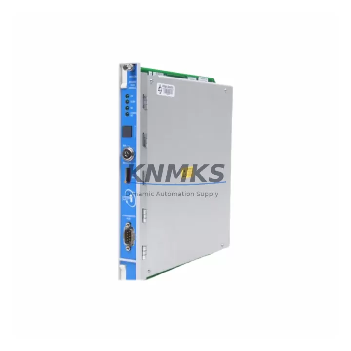
Bently Nevada 3500/32-01-01 Maintenance-Proven Spare Part for Factory Uptime
The Bently Nevada 3500/32-01-01 (part numbers 149986-02 + 125720-01) is a 4-channel relay output module designed for the Bently Nevada 3500 Series machinery protection system — one of the most widely deployed continuous vibration monitoring platforms in rotating equipment facilities worldwide. Maintaining a verified, pre-tested spare of this module is a foundational step in any reliability-centered maintenance (RCM) program for turbines, compressors, pumps, and generators operating in oil & gas, petrochemical, power generation, and heavy industrial environments.
When this relay output module fails or degrades, the entire protection channel it governs — including trip relay logic, alarm relay outputs, and system-level interlock signaling — is compromised. Unplanned downtime caused by a missing or untested spare can extend from hours to days when sourcing from standard distribution channels. Stocking a certified replacement eliminates that risk entirely and allows maintenance teams to execute a controlled swap during the next available maintenance window or immediately during an emergency shutdown.
Every unit supplied by KNMKS is sourced from verified channels, subjected to pre-shipment functional testing, and backed by a support terms confirmed by quotation. Global dispatch is available to support both scheduled outages and emergency replacement scenarios.
Spare Maintenance Table
| Parameter | Specification |
|---|---|
| Part Number | 149986-02 + 125720-01 |
| SKU | 3500/32-01-01 |
| Brand | Bently Nevada |
| Series | 3500 Series Machinery Protection System |
| Module Type | 4-Channel Relay Output Module |
| Output Channels | 4 independent relay outputs (alarm/trip) |
| Relay Type | Form C (SPDT) dry contact relays |
| Contact Rating | 5 A @ 250 VAC / 30 VDC (resistive load) |
| Backplane Compatibility | 3500 Series 19-slot and 3-slot rack backplanes |
| Communication Interface | Internal rack bus (non-isolated) |
| Operating Temperature | 0°C to +60°C |
| Humidity | 5% to 95% RH, non-condensing |
| Country of Origin | United States |
| Condition | Original, pre-tested |
| Support terms | 12 months from date of shipment |
| Shipping | Global dispatch, DHL / FedEx priority available |
| Application | Turbines, compressors, pumps, generators — vibration protection systems |
Maintenance Planning for Continuous Operation
Replacing the 3500/32-01-01 relay output module is rarely an isolated task. In a properly maintained 3500 Series rack, the relay output module works in close coordination with several adjacent components that should be inspected or tested concurrently to ensure the protection system is fully restored to specification.
Begin with the 3500/20 rack power supply module — relay output modules are sensitive to power rail quality, and a degraded or aging power supply can cause intermittent relay chatter or false trip events even after a module swap. Verify DC bus voltage stability before declaring the replacement successful.
Next, inspect the 3500/22M transient data interface (TDI) or the relevant monitor module (such as the 3500/42M proximitor/seismic monitor or 3500/40M proximitor monitor) that feeds alarm and trip logic to the relay output module. If the monitor module has accumulated fault history or is approaching its recommended service interval, replacing it alongside the relay output module eliminates a second unplanned outage.
Check the 3500 Series I/O terminal blocks and field wiring terminations connected to the relay output channels. Corroded terminals, loose field wiring, or degraded cable insulation are common root causes of relay output failures that are misattributed to the module itself. Cleaning and re-torquing all terminal connections during the replacement window is a low-cost, high-value step.
For facilities running the 3500 system with a 3500/92 communication gateway module (Modbus, Profibus, or Ethernet/IP), verify that the gateway firmware and configuration are compatible with the replacement module’s relay mapping. Mismatched relay channel assignments can cause silent alarm suppression — a critical safety risk in trip-critical applications.
Finally, review the system rack backplane for signs of connector wear, oxidation on the module edge connectors, or physical damage to the backplane bus. A worn backplane can cause intermittent communication faults that mimic relay output module failures and will recur regardless of how many modules are replaced.
Stocking the 3500/32-01-01 as part of a broader 3500 Series critical spares kit — alongside the power supply, at least one monitor module, and the communication gateway — is the recommended approach for facilities where unplanned downtime carries significant production or safety consequences.
Site Replacement Workflow
Step 1 — Pre-replacement verification: Confirm the replacement module part numbers (149986-02 + 125720-01) match the installed module label. Cross-reference the rack slot assignment in the 3500 System configuration software (System 1 or Rack Configuration Software) to ensure relay channel mapping is preserved after the swap.
Step 2 — Safe isolation: Follow site-specific LOTO (lockout/tagout) procedures. For hot-swap capable racks, verify that the specific slot supports live removal before proceeding without a full system shutdown. Most 3500 relay output module replacements require a controlled rack power-down to avoid spurious trip signals during extraction.
Step 3 — Module extraction and inspection: Remove the faulty module and inspect the backplane connector for bent pins or contamination. Clean with appropriate contact cleaner if required. Document the fault condition and any error codes displayed on the rack status indicators.
Step 4 — Replacement installation: Seat the new 3500/32-01-01 module firmly into the rack slot. Restore power and observe the module status LED sequence. A solid green status LED indicates successful initialization and communication with the rack processor.
Step 5 — Functional verification: Using the 3500 Rack Configuration Software, perform a relay output functional test on all four channels. Verify that alarm and trip setpoints are correctly loaded from the rack configuration and that field device responses (shutdown valves, annunciators, DCS inputs) are confirmed at the field level.
Step 6 — Documentation and return to service: Update the maintenance management system (CMMS) with the replacement record, new module serial number, and test results. Return the system to normal monitoring mode and confirm with the control room that all protection channels are active.
Spare Parts Support FAQ
Q1: Is the 3500/32-01-01 a direct drop-in replacement for older 3500/32 relay output modules?
The 3500/32-01-01 (149986-02 + 125720-01) is the current production variant of the 3500/32 relay output module family. It is backward-compatible with standard 3500 Series 19-slot and 3-slot rack configurations. However, always verify the rack configuration software version and relay channel mapping before installation, as firmware-level differences between early and late production variants may require a configuration update.
Q2: How do you verify the module is genuine and pre-tested before shipment?
All KNMKS-supplied 3500/32-01-01 modules undergo pre-shipment functional testing that includes relay contact continuity verification, coil energization testing, and visual inspection of the PCB and edge connector. A test report is available upon request. Modules are shipped in anti-static packaging with tamper-evident labeling to ensure integrity during transit.
Q3: What is the recommended spare holding strategy for 3500 Series relay output modules?
For facilities operating more than two 3500 Series racks, maintaining a minimum of one 3500/32-01-01 spare per rack type is recommended. For single-rack critical applications (e.g., main turbine protection), holding two spares is advisable to cover both an emergency replacement and a subsequent planned maintenance cycle. Spares should be stored in a climate-controlled environment and inspected annually.
Q4: What is the support terms coverage and what does it include?
All units carry a support terms confirmed by quotation from the date of shipment. The support terms covers manufacturing defects, relay contact failure under normal operating conditions, and PCB-level component failures. It does not cover damage resulting from incorrect installation, overvoltage events, or physical mishandling. Support requests are processed within 5 business days, with advance replacement available for critical applications upon request.
© 2026 KNMKS. All rights reserved.
Original Source: https://knmks.com
Contact: admin@knmks.com | +86 18359268345
Product Identification
- Brand / Ecosystem
-
Bently Nevada
Bently Nevada - Model / Series
-
3500/32-01-01 149986-02+125720-01
3500 Series - Product Family
- PLCs & Controllers
- Availability Status
- Available on request after model and quantity confirmation
- Inquiry Type
- B2B RFQ, replacement inquiry and project spare-part request
- Pre-Quote Check
- Exact SKU, brand, series, quantity, nameplate photos and destination country are checked before quotation
System Path
Where this product fits in the KNMKS automation structure.
Specification & Inquiry Focus
- Control platform
- PLC, PAC and modular controllers
- Common needs
- CPU, rack, power and I/O expansion
- Project support
- Replacement, cabinet build and maintenance
Buyer Confirmation
Information KNMKS checks before replying.
- Exact model
- 3500/32-01-01 149986-02+125720-01
- Brand / ecosystem
- Bently Nevada
- Product family
- PLCs & Controllers
- Application note
- Replacement, maintenance, project build or spare-part list
- Useful photos
- Nameplate, installed unit, cabinet layout or connector side
- Delivery details
- Quantity, destination country and target schedule
Document Support
Files and notes can be confirmed during quotation.
- Product photos or nameplate confirmation when available
- Packing and delivery notes before quotation confirmation
- Support scope and delivery terms confirmed per inquiry
- Export document coordination for qualified B2B requests
Inquiry Support
- Model cross-checking before quotation
- CPU, power, rack and expansion module matching
- Support for replacement and project inquiry
What to Send Us
- Brand and exact model number: Bently Nevada 3500/32-01-01 149986-02+125720-01
- Quantity and required delivery time
- Application, replacement requirement or nameplate photo
- Destination country and shipping preference
RFQ Preparation
This is a product inquiry page built for RFQ communication.
Fast Model Check
Send this model to KNMKS for confirmation.
Include quantity, destination country and photos if this is a maintenance replacement. The inquiry will be saved with a reference number after submission.
Brand & Compatibility Note
KNMKS displays automation product information for well-known industrial brand ecosystems and compatible replacement references. Brand names are used for product identification and compatibility reference only; final availability and commercial terms are confirmed per quotation.
 Manufacturing
 Machine Tools
 Packaging
 Energy & Power
 HMI & Displays
 Servo Systems
 Variable Frequency Drives
 Sensors