
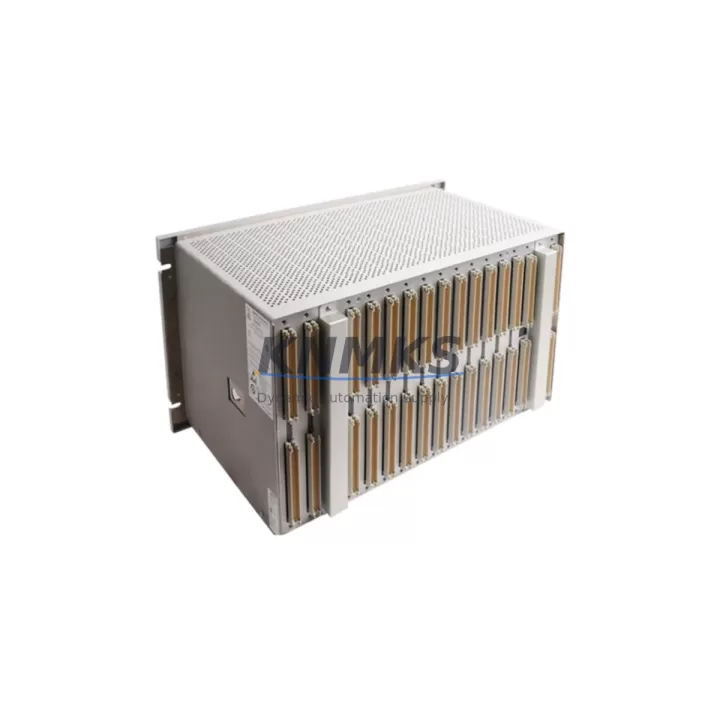
Overview
Bently Nevada 3500/05-02-04-00-00-01 Migration-Ready Power Monitor for Legacy Control Systems
The Bently Nevada 3500/05-02-04-00-00-01 is a rack-mount power monitor module engineered for the 3500 Series machinery protection platform. As legacy installations age and OEM support windows close, this module serves as a verified drop-in replacement for facilities managing long-lifecycle rotating equipment — including turbines, compressors, pumps, and generators. Whether you are executing a planned retrofit, responding to an unplanned failure, or building a strategic spare parts buffer, the 3500/05-02-04-00-00-01 is a field-proven solution that preserves your existing rack architecture and minimizes engineering rework.
Before installation, engineers should confirm power supply capacity within the 3500 rack chassis. The 3500/05-02-04-00-00-01 draws from the rack’s internal DC bus, and any co-installed modules — such as the 3500/15 Power Supply, 3500/22M Transient Data Interface, or 3500/42M Proximitor/Seismic Monitor — must be accounted for in the total power budget. Overloading the rack bus is a common oversight during rushed retrofits and can cause intermittent resets or protection channel dropouts.
Terminal wiring compatibility should be verified against the original rack wiring diagram. The 3500/05-02-04-00-00-01 uses the standard 3500 Series I/O terminal block format, which is compatible with existing field cable terminations in most installations. However, if the rack was previously configured with an earlier revision of the power monitor, technicians should inspect terminal block pin assignments for any revision-specific differences before energizing the replacement module.
Backplane slot assignment and module addressing must be confirmed in the System 1 or Rack Configuration Software prior to commissioning. The 3500/05-02-04-00-00-01 occupies a dedicated slot in the 3500 rack and its address is recognized automatically by the rack’s configuration firmware. If the rack is running an older firmware version, a firmware compatibility check against the module’s hardware revision is recommended before final installation. Mismatched firmware can prevent the module from being recognized by the 3500/20 Rack Interface Module or the 3500/92 Communication Gateway.
For sites integrating the 3500 platform with a DCS or SCADA system via Modbus, PROFIBUS, or Ethernet/IP, the 3500/92 Communication Gateway should be verified for protocol mapping continuity after the power monitor swap. Communication link integrity is especially critical in installations where the power monitor’s status outputs feed interlock logic in a PLC or safety instrumented system. HMI screens that display rack power status should be tested post-commissioning to confirm that all data tags are resolving correctly and that no alarm suppression is inadvertently active.
Installation space within the control cabinet should be confirmed before ordering. The 3500/05-02-04-00-00-01 occupies a standard single-slot position in the 3500 rack. If the rack is mounted in a congested panel alongside other Bently Nevada modules such as the 3500/40M Proximitor Monitor or 3500/50 Tachometer, ensure adequate clearance for module extraction and re-insertion without disturbing adjacent wiring harnesses.
Migration Compatibility Table
| Parameter | Details |
|---|---|
| Compatible Rack | Bently Nevada 3500 Series Rack |
| Slot Type | Single-slot, standard 3500 backplane |
| Power Interface | Internal DC bus via 3500 rack backplane |
| Communication Compatibility | Modbus RTU, PROFIBUS DP, Ethernet/IP (via 3500/92 Gateway) |
| Firmware Compatibility | Verify rack firmware revision before installation |
| Terminal Block Format | Standard 3500 Series I/O terminal block |
| Replacement Scope | Drop-in replacement for legacy 3500/05 power monitor variants |
| Commissioning Tool | Rack Configuration Software / System 1 |
| Installation Space | Single rack slot; confirm panel clearance |
| Support terms | support terms confirmed by quotation — all units ship tested and verified |
Retrofit Planning for Existing Automation Systems
A successful retrofit of the 3500/05-02-04-00-00-01 requires a structured pre-outage planning process. Begin by auditing the full rack population: document every installed module, its slot position, firmware revision, and current alarm setpoints. Common co-installed modules in a 3500 rack include the 3500/15 Power Supply, 3500/20 Rack Interface Module, 3500/22M Transient Data Interface, 3500/40M Proximitor Monitor, 3500/42M Proximitor/Seismic Monitor, and 3500/50 Tachometer. Each of these modules has interdependencies with the power monitor that must be understood before the outage window begins.
If the site uses a 3500/92 Communication Gateway for DCS integration, export the current rack configuration file from the Rack Configuration Software before any hardware changes. This file serves as the baseline for post-retrofit verification and allows rapid restoration if the new module requires configuration adjustments. For sites using System 1 software for condition monitoring, confirm that the historian tags associated with the power monitor channel are mapped correctly and that no data gaps will be introduced during the swap.
Signal isolators or barriers installed between the 3500 rack and field instruments should be inspected as part of the retrofit scope. Aging signal conditioning hardware can introduce noise or offset errors that are masked by a failing power monitor but become visible after a clean replacement is installed. Addressing these upstream signal quality issues during the planned outage avoids a second unplanned shutdown shortly after the retrofit.
Programming cable access for the rack should be confirmed in advance. If the 3500/20 Rack Interface Module requires a configuration push after the power monitor replacement, the RS-232 or Ethernet programming port must be accessible without panel disassembly. Pre-staging the laptop with the correct version of Rack Configuration Software and the saved configuration file eliminates delays during the commissioning phase.
Downtime Control During System Migration
Minimizing downtime during a 3500/05-02-04-00-00-01 replacement begins with pre-staging. The replacement module should be bench-tested and verified against the rack’s configuration file before the outage window opens. All terminal block wiring should be photographed and labeled before disconnection. If the site operates a redundant protection channel, confirm that the redundant path is active and healthy before taking the primary power monitor offline.
Original program logic in the connected PLC or safety system should not be modified during the power monitor swap. The 3500 rack’s protection outputs — including relay contacts feeding interlock circuits — should be bypassed according to the site’s management of change procedure before the module is extracted. This prevents spurious trips to the connected machinery during the physical swap.
Post-installation, the commissioning sequence should follow the rack’s standard power-up procedure: apply rack power, confirm module recognition in the Rack Configuration Software, verify all channel OK indicators, and restore any bypassed protection outputs in sequence. HMI screens displaying rack power status should be checked for correct tag resolution before the outage is formally closed. A final walk-down of the control cabinet to confirm all terminal connections are secure and no tools or foreign objects remain in the panel completes the commissioning record.
All units supplied by KNMKS are pre-tested prior to shipment. In-stock inventory supports rapid dispatch to minimize the gap between order placement and site delivery, directly reducing the total duration of planned and unplanned outages.
Retrofit Support FAQ
Q: Is the 3500/05-02-04-00-00-01 a direct replacement for earlier 3500/05 power monitor variants?
A: In most installations, yes. The 3500/05-02-04-00-00-01 is designed for the standard 3500 rack backplane and uses the same terminal block format as earlier 3500/05 variants. However, firmware revision compatibility should be confirmed against the rack’s current firmware version before installation, particularly on older rack assemblies that have not been updated in several years.
Q: What commissioning steps are required after installing the replacement module?
A: After physical installation, power up the rack and confirm module recognition in the Rack Configuration Software or System 1. Verify all channel OK indicators, check alarm setpoints against the saved configuration baseline, and confirm communication link integrity through the 3500/92 Gateway if applicable. Restore any bypassed protection outputs in sequence and document the commissioning record.
Q: How do I verify terminal wiring compatibility before the outage?
A: Compare the terminal block pin assignment diagram for the 3500/05-02-04-00-00-01 against the existing rack wiring documentation. Photograph all existing terminations before disconnection. If the original wiring documentation is unavailable, a point-to-point continuity check of each terminal against the field cable schedule is recommended before energizing the replacement module.
Q: What support terms and supply terms apply to this module?
A: All 3500/05-02-04-00-00-01 units supplied by KNMKS carry a support terms confirmed by quotation covering manufacturing defects and functional performance. Units are pre-tested prior to shipment. In-stock availability supports rapid dispatch. Contact admin@knmks.com or +86 18359268345 for current stock status and lead time confirmation.
© 2026 KNMKS. All rights reserved.
Original Source: https://knmks.com
Contact: admin@knmks.com | +86 18359268345
Product Identification
- Brand / Ecosystem
-
Bently Nevada
Bently Nevada - Model / Series
-
3500/05-02-04-00-00-01
3500 Series - Product Family
- PLCs & Controllers
- Availability Status
- Available on request after model and quantity confirmation
- Inquiry Type
- B2B RFQ, replacement inquiry and project spare-part request
- Pre-Quote Check
- Exact SKU, brand, series, quantity, nameplate photos and destination country are checked before quotation
System Path
Where this product fits in the KNMKS automation structure.
Specification & Inquiry Focus
- Control platform
- PLC, PAC and modular controllers
- Common needs
- CPU, rack, power and I/O expansion
- Project support
- Replacement, cabinet build and maintenance
Buyer Confirmation
Information KNMKS checks before replying.
- Exact model
- 3500/05-02-04-00-00-01
- Brand / ecosystem
- Bently Nevada
- Product family
- PLCs & Controllers
- Application note
- Replacement, maintenance, project build or spare-part list
- Useful photos
- Nameplate, installed unit, cabinet layout or connector side
- Delivery details
- Quantity, destination country and target schedule
Document Support
Files and notes can be confirmed during quotation.
- Product photos or nameplate confirmation when available
- Packing and delivery notes before quotation confirmation
- Support scope and delivery terms confirmed per inquiry
- Export document coordination for qualified B2B requests
Inquiry Support
- Model cross-checking before quotation
- CPU, power, rack and expansion module matching
- Support for replacement and project inquiry
What to Send Us
- Brand and exact model number: Bently Nevada 3500/05-02-04-00-00-01
- Quantity and required delivery time
- Application, replacement requirement or nameplate photo
- Destination country and shipping preference
RFQ Preparation
This is a product inquiry page built for RFQ communication.
Fast Model Check
Send this model to KNMKS for confirmation.
Include quantity, destination country and photos if this is a maintenance replacement. The inquiry will be saved with a reference number after submission.
Brand & Compatibility Note
KNMKS displays automation product information for well-known industrial brand ecosystems and compatible replacement references. Brand names are used for product identification and compatibility reference only; final availability and commercial terms are confirmed per quotation.
 Manufacturing
 Machine Tools
 Packaging
 Energy & Power
 HMI & Displays
 Servo Systems
 Variable Frequency Drives
 Sensors