
Overview
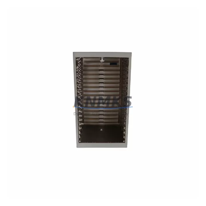
Bently Nevada 3500/05-01-01-00-00-01 Migration-Ready 14-Slot Rack: Legacy System Upgrade & Compatible Replacement
The Bently Nevada 3500/05-01-01-00-00-01 is a 14-slot main power supply rack designed for the 3500 Series Machinery Protection System (MPS). As rotating equipment monitoring platforms age beyond their supported lifecycle, engineering teams face increasing pressure to source verified replacement racks that maintain signal integrity, backplane compatibility, and communication continuity with existing 3500 Series monitor modules. This unit is stocked, pre-tested, and ready for immediate dispatch to support both emergency replacements and planned outage windows.
The 3500/05-01-01-00-00-01 rack serves as the structural and electrical backbone of the 3500 Series chassis. It houses up to 14 modules — including the 3500/15 Power Supply, 3500/20 Rack Interface Module (RIM), 3500/22M Transient Data Interface, 3500/40M Proximitor/Seismic Monitor, and 3500/42M Proximitor/Seismic Monitor — all of which slot directly into the backplane without requiring re-wiring of field termination assemblies (FTAs) when the rack itself is replaced. This is a critical advantage during time-constrained outages: the FTA wiring remains intact, and only the rack and its installed modules need to be swapped and re-addressed.
Before committing to a rack replacement, engineering teams should verify several key parameters. Power supply capacity must be confirmed against the total module load — the 3500/15 Power Supply module’s output rating must support all installed monitor cards simultaneously. Backplane slot addressing must be re-confirmed after installation, as the 3500/20 RIM stores rack and slot configuration data that may need to be re-entered via the Rack Configuration Software (RCS) if the replacement rack has a different firmware baseline. Terminal block wiring on the FTAs should be inspected for corrosion or loose connections before the new rack is energized, particularly in high-vibration or high-humidity environments.
Communication link continuity is another migration checkpoint. If the existing installation uses the 3500/20 RIM’s Modbus RTU or Ethernet/IP interface to feed data to a DCS or historian, the IP address, node ID, and polling configuration must be re-validated after rack replacement. In plants running Bently Nevada System 1 software for condition monitoring, the rack’s communication parameters must match the System 1 database configuration to avoid alarm suppression or data gaps during the transition period.
Installation space confirmation is straightforward for like-for-like rack replacements: the 3500/05-01-01-00-00-01 maintains the same DIN-rail and panel-mount footprint as earlier 3500 Series rack variants. However, if the replacement is part of a broader control cabinet upgrade — for example, consolidating multiple legacy racks into a single enclosure — rack orientation, cooling airflow direction, and cable management must be re-evaluated. The 3500 Series rack requires adequate vertical clearance for module extraction during future maintenance cycles.
Firmware version compatibility should be checked before powering the replacement rack. If the installed 3500/20 RIM or 3500/22M Transient Data Interface modules carry firmware versions that differ from those validated against the plant’s System 1 software version, a firmware update may be required before the rack is returned to service. Our pre-shipment testing process includes a functional power-on check and module slot verification, but site-specific firmware alignment remains the responsibility of the commissioning engineer.
All units are supplied with a support terms confirmed by quotation covering manufacturing defects and backplane integrity. Multi-region stock is maintained to support fast global dispatch for both scheduled outages and emergency breakdowns.
Migration Compatibility Table
| Parameter | Details |
|---|---|
| SKU | 3500/05-01-01-00-00-01 |
| Brand / Series | Bently Nevada / 3500 Series MPS |
| Rack Slots | 14 slots (main power supply rack) |
| Compatible Modules | 3500/15, 3500/20, 3500/22M, 3500/40M, 3500/42M and other 3500 Series monitors |
| Backplane Interface | 3500 Series proprietary backplane; FTA wiring preserved on replacement |
| Communication Compatibility | Modbus RTU, Ethernet/IP via 3500/20 RIM; System 1 software compatible |
| Installation | Panel-mount / DIN-rail; same footprint as legacy 3500/05 variants |
| Power Supply Module | Requires 3500/15 Power Supply; verify load capacity before energizing |
| Firmware Note | Confirm RIM and TDI firmware versions match System 1 software baseline |
| Replacement Recommendation | Like-for-like drop-in; re-address rack/slot config via RCS after installation |
| Commissioning Checkpoint | Verify FTA terminal integrity, communication link, alarm setpoints, and HMI tags |
| Pre-Shipment Testing | Functional power-on check and slot verification included |
| Support terms | 12 months from shipment date |
| Origin | USA |
| Stock Status | availability confirmed by RFQ; multi-region dispatch available |
Retrofit Planning for Existing Automation Systems
A successful 3500/05-01-01-00-00-01 rack replacement begins well before the outage window opens. The first step is a full module inventory of the existing rack: document every installed card by slot position, including the 3500/20 Rack Interface Module, any 3500/40M or 3500/42M Proximitor/Seismic Monitor cards, and the 3500/15 Power Supply. Photograph the FTA terminal wiring and record the rack configuration data from the RCS before powering down — this data will be re-entered into the replacement rack after installation.
If the plant’s condition monitoring architecture includes a 3500/22M Transient Data Interface for waveform capture, confirm that the replacement rack’s backplane revision is compatible with the TDI’s firmware. In some legacy installations, the TDI is paired with a dedicated 3500/20 RIM on a separate communication segment; this topology must be preserved in the replacement rack layout to avoid data routing conflicts in System 1.
For plants that have already migrated their DCS to a modern platform — such as a Honeywell Experion PKS or an Emerson DeltaV — the 3500 Series rack’s Modbus or Ethernet/IP output typically feeds a dedicated I/O card or OPC server. Verify that the communication parameters (baud rate, parity, node address, or IP/subnet) are documented before the rack is removed, and re-validate the link from the DCS side after the replacement rack is commissioned. HMI faceplates that display vibration, speed, or position data from the 3500 Series monitors should be checked for tag mapping accuracy after the rack is returned to service.
In control cabinet upgrades where the 3500 rack shares an enclosure with other legacy equipment — such as a Woodward 505 speed controller, a Triconex TMR safety controller, or a GE Speedtronic Mark V turbine control panel — installation space and cable routing must be re-evaluated. Ensure that the replacement rack’s cooling airflow is not obstructed by adjacent equipment and that the power distribution within the cabinet can support the combined load of all installed modules.
Signal isolators installed between the 3500 Series FTAs and field sensors (proximity probes, velocity transducers, or accelerometers) should be inspected during the rack replacement outage. If any isolator shows signs of drift or degradation, replacing it concurrently with the rack minimizes future unplanned downtime. Programming cables and laptop-based RCS access should be prepared in advance so that rack configuration, alarm setpoints, and communication parameters can be re-entered and verified within the planned outage window.
Downtime Control During System Migration
Minimizing downtime during a 3500/05-01-01-00-00-01 rack replacement requires a structured pre-outage preparation protocol. Before the machine is taken offline, export the full rack configuration from the RCS software and save it to a secure backup location. This configuration file contains all channel assignments, alarm setpoints, transducer parameters, and communication settings — it is the fastest path to restoring the rack to its pre-outage state after the replacement unit is installed.
During the physical swap, keep the FTA wiring intact wherever possible. The 3500 Series architecture separates the rack and modules from the field wiring via FTAs, which means the replacement rack can be installed and the modules re-seated without disturbing the sensor cables at the terminal blocks. This significantly reduces the risk of wiring errors and shortens the time required to return the machine to monitored operation.
After the replacement rack is powered on and the modules are re-seated, use the RCS to re-enter the rack configuration from the saved backup. Verify each channel’s OK status, confirm that the 3500/20 RIM has re-established its communication link to the DCS or historian, and check that all alarm setpoints are active and correctly mapped. If the plant uses System 1 for online condition monitoring, confirm that the rack is visible in the System 1 database and that waveform data is being received from the 3500/22M TDI before releasing the machine to operations.
A parallel hot-standby approach — where the replacement rack is pre-configured and bench-tested before the outage — further compresses the on-site commissioning time. Our pre-shipment testing process supports this workflow: each unit is powered on and slot-verified before dispatch, so the replacement rack arrives ready for configuration loading rather than requiring a cold-start diagnostic cycle on site.
Retrofit Support FAQ
Q: Is the 3500/05-01-01-00-00-01 a direct drop-in replacement for other 3500/05 rack variants?
A: Yes, for most 3500 Series installations. The -01-01-00-00-01 suffix indicates the standard AC/DC power input and non-isolated backplane configuration. Verify your existing rack’s suffix against the replacement unit before ordering to confirm power input compatibility. FTA wiring and module slot assignments are preserved across compatible 3500/05 variants.
Q: Do I need to re-configure the rack after installation?
A: Yes. The 3500/20 Rack Interface Module stores rack and slot configuration data. After installing the replacement rack and re-seating all modules, use the Rack Configuration Software (RCS) to re-enter the configuration from your pre-outage backup. Alarm setpoints, transducer parameters, and communication settings must all be verified before returning the machine to service.
Q: What pre-shipment testing is performed on this unit?
A: Each 3500/05-01-01-00-00-01 rack undergoes a functional power-on check and backplane slot verification before dispatch. Units are inspected for physical integrity and connector condition. A support terms confirmed by quotation is included from the shipment date, covering manufacturing defects and backplane integrity.
Q: How quickly can this unit be dispatched for an emergency replacement?
A: Stock is maintained across multiple regions to support fast global dispatch. Emergency orders are prioritized for same-day or next-business-day shipment where stock is available at the nearest regional warehouse. Contact our team with your delivery location and urgency level to confirm lead time.
© 2026 KNMKS. All rights reserved.
Original Source: https://knmks.com
Contact: admin@knmks.com | +86 18359268345
Product Identification
- Brand / Ecosystem
-
Bently Nevada
Bently Nevada - Model / Series
-
3500/05-01-01-00-00-01
3500 Series - Product Family
- PLCs & Controllers
- Availability Status
- Available on request after model and quantity confirmation
- Inquiry Type
- B2B RFQ, replacement inquiry and project spare-part request
- Pre-Quote Check
- Exact SKU, brand, series, quantity, nameplate photos and destination country are checked before quotation
System Path
Where this product fits in the KNMKS automation structure.
Specification & Inquiry Focus
- Control platform
- PLC, PAC and modular controllers
- Common needs
- CPU, rack, power and I/O expansion
- Project support
- Replacement, cabinet build and maintenance
Buyer Confirmation
Information KNMKS checks before replying.
- Exact model
- 3500/05-01-01-00-00-01
- Brand / ecosystem
- Bently Nevada
- Product family
- PLCs & Controllers
- Application note
- Replacement, maintenance, project build or spare-part list
- Useful photos
- Nameplate, installed unit, cabinet layout or connector side
- Delivery details
- Quantity, destination country and target schedule
Document Support
Files and notes can be confirmed during quotation.
- Product photos or nameplate confirmation when available
- Packing and delivery notes before quotation confirmation
- Support scope and delivery terms confirmed per inquiry
- Export document coordination for qualified B2B requests
Inquiry Support
- Model cross-checking before quotation
- CPU, power, rack and expansion module matching
- Support for replacement and project inquiry
What to Send Us
- Brand and exact model number: Bently Nevada 3500/05-01-01-00-00-01
- Quantity and required delivery time
- Application, replacement requirement or nameplate photo
- Destination country and shipping preference
RFQ Preparation
This is a product inquiry page built for RFQ communication.
Fast Model Check
Send this model to KNMKS for confirmation.
Include quantity, destination country and photos if this is a maintenance replacement. The inquiry will be saved with a reference number after submission.
Brand & Compatibility Note
KNMKS displays automation product information for well-known industrial brand ecosystems and compatible replacement references. Brand names are used for product identification and compatibility reference only; final availability and commercial terms are confirmed per quotation.
 Manufacturing
 Machine Tools
 Packaging
 Energy & Power
 HMI & Displays
 Servo Systems
 Variable Frequency Drives
 Sensors