
Overview
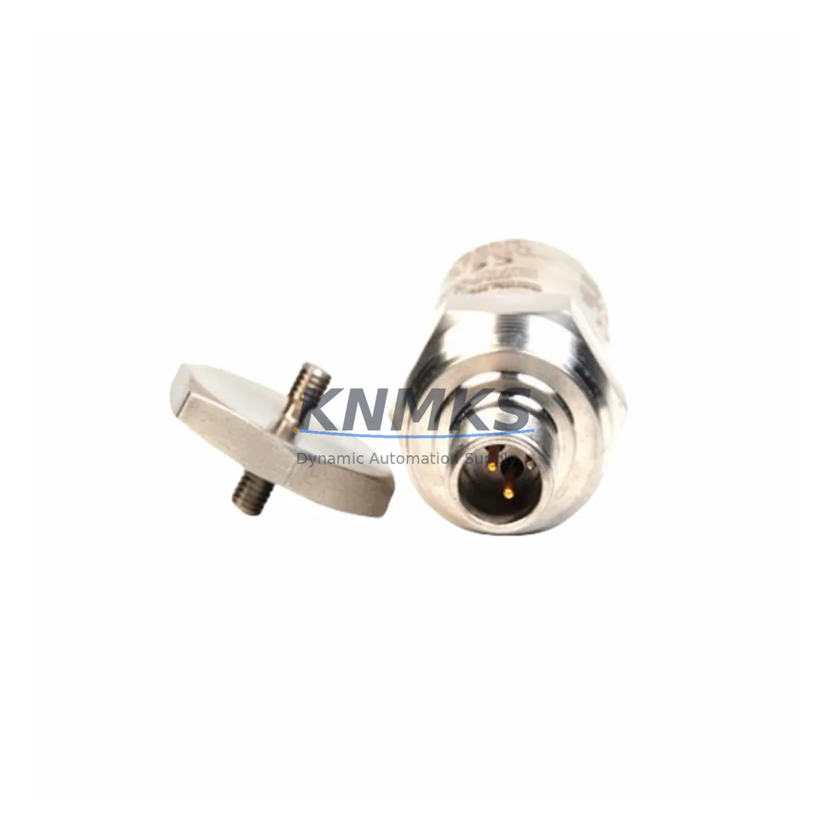
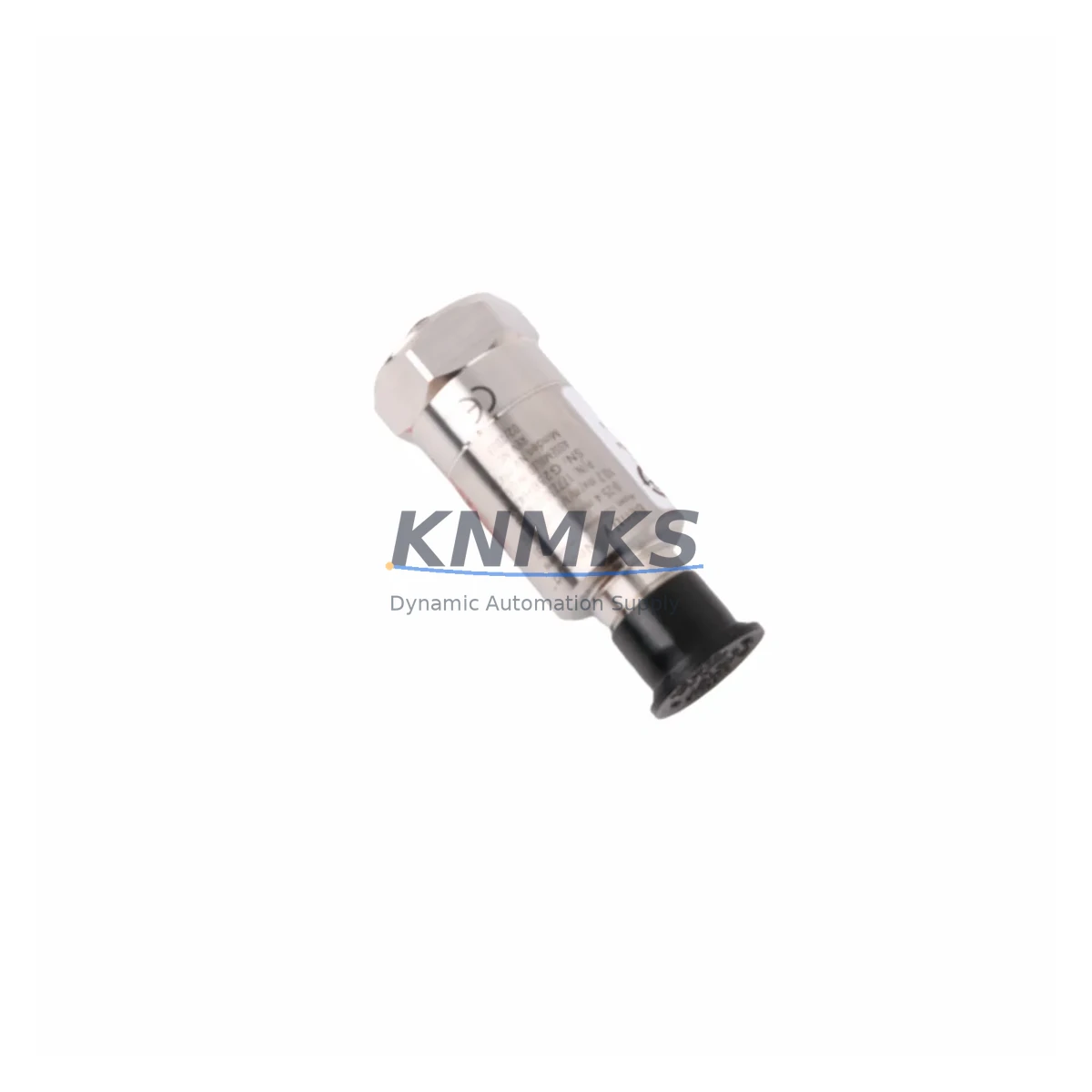
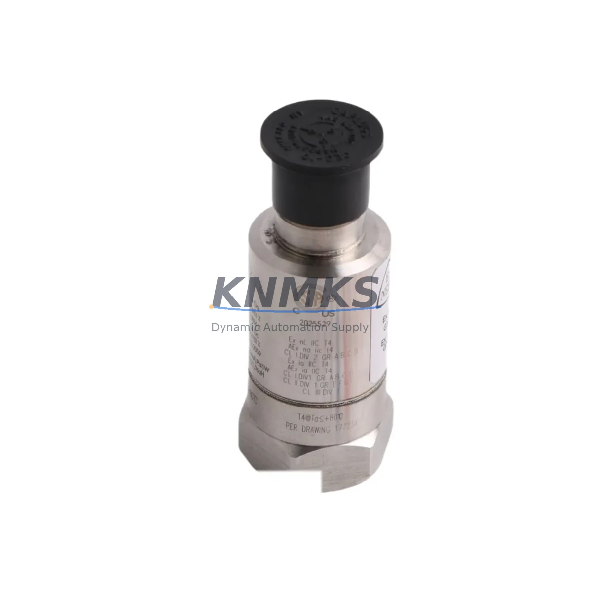
Bently Nevada 190501-00-00-CN Migration-Ready Seismic Velocity Transducer for Legacy Control Systems
The Bently Nevada 190501-00-00-CN is a Velomitor CT piezoelectric velocity transducer engineered for direct retrofit into existing Bently Nevada 3500 and 3300 Series continuous monitoring systems. As legacy seismic monitoring infrastructure reaches end-of-support, plant engineers face increasing pressure to source pre-tested, drop-in compatible replacements that preserve existing wiring, barrier configurations, and monitor rack assignments without requiring full system redesign. The 190501-00-00-CN addresses this need with a migration-ready form factor, calibrated output sensitivity, and full compatibility with the 3500/42M Proximitor/Seismic Monitor and 3300/16 Seismic Monitor modules already installed in the field.
This transducer delivers a 100 mV/in/s (4 mV/mm/s) output sensitivity across a frequency range of 2 to 1000 Hz, making it a functionally equivalent replacement for earlier Velomitor and standard velocity transducer variants used in turbine, compressor, pump, and motor bearing housings. Engineers migrating from older 3300 Series racks to 3500 Series architectures will find the 190501-00-00-CN compatible with both platforms, reducing the scope of hardware changes during phased upgrades. The transducer’s integral cable and connector configuration matches the standard Bently Nevada field wiring convention, allowing technicians to reuse existing conduit runs and terminal block assignments in most installations.
Before installation, engineers should verify the existing barrier or I/O module — typically a 3500/32 4-Channel Relay Module or a 3500/22M Transient Data Interface — is configured for the correct input impedance and signal range. Where Zener barriers or galvanic isolators are present in the loop, confirm that the barrier’s voltage and current limits remain within the transducer’s operating envelope. Firmware version checks on the 3500/42M monitor card are recommended to ensure the channel configuration aligns with the transducer’s output type prior to commissioning.
Migration Compatibility Table
| Parameter | 190501-00-00-CN Specification | Retrofit Notes |
|---|---|---|
| Output Sensitivity | 100 mV/in/s (4 mV/mm/s) | Verify monitor channel scale factor matches; reconfigure 3500/42M if migrating from non-Velomitor CT variant |
| Frequency Range | 2 – 1000 Hz | Confirm alarm setpoints in 3500 rack are within this band; adjust if previously set for narrower-range sensors |
| Operating Temperature | -40°C to +121°C | Suitable for most turbine bearing housings; confirm ambient temperature at installation point |
| Connector / Cable | Integral armored cable, MIL-C-5015 style connector | Reuse existing conduit and terminal block in most cases; check connector gender and pin-out against field wiring |
| Compatible Monitors | 3500/42M, 3300/16, 3500/22M | No rack modification required for direct channel swap; update channel configuration in System 1 software if applicable |
| Barrier Compatibility | Standard Zener barrier / galvanic isolator loops | Confirm barrier voltage/current ratings; replace MTL or P+F barriers if aged beyond service life |
| Installation Interface | 1/4-28 UNF threaded stud mount | Verify mounting pad thread condition; use thread insert if housing is worn |
| Support terms | 12 Months | Covers manufacturing defects; pre-shipment functional test included |
Retrofit Planning for Existing Automation Systems
A successful retrofit of the 190501-00-00-CN into an operating plant begins with a thorough audit of the existing monitoring loop. Engineers should document the current channel assignment within the 3500 rack, noting the slot position of the 3500/42M Proximitor/Seismic Monitor and the associated I/O module. Where the plant runs Bently Nevada System 1 condition monitoring software, the channel database entry for the replaced transducer must be updated to reflect the 190501-00-00-CN’s sensitivity and serial number to maintain data continuity and alarm history integrity.
In installations where the seismic transducer shares a junction box with proximity probes — such as a 3300 XL 8mm or 3300 XL 11mm proximity system monitoring shaft displacement — technicians must take care to isolate the velocity transducer loop during replacement to avoid introducing noise into adjacent proximity channels. The 3500/15 Power Supply module feeding the rack should be checked for available current headroom if additional I/O cards are being added as part of a broader upgrade scope.
For plants migrating from older 3300 Series racks to a 3500 Series architecture, the 190501-00-00-CN can be installed on the machine prior to rack cutover, allowing pre-commissioning signal checks using a portable vibration analyzer. This approach reduces the live cutover window and allows engineering teams to confirm transducer output, cable continuity, and connector integrity before the new rack goes online. Where a 3500/20 Rack Configuration Module is used, ensure the rack configuration file is updated and validated in Rack Configuration software before energizing the new system.
Signal isolation requirements should also be reviewed during planning. If the plant uses a DCS interface — such as a Honeywell Experion PKS or an ABB 800xA integration — the 4–20 mA output from the 3500/42M monitor card feeding the DCS I/O module must be re-ranged if the new transducer’s full-scale output differs from the previous configuration. Confirm the DCS tag scaling and alarm limits in the engineering workstation before returning the machine to service.
Downtime Control During System Migration
Minimizing unplanned downtime during a seismic transducer replacement requires a structured pre-outage preparation process. Before the maintenance window opens, the replacement 190501-00-00-CN should be bench-tested using a signal simulator or calibrated shaker to confirm output sensitivity and frequency response. All spare connectors, cable glands, and thread adapters should be staged at the work site to avoid delays caused by missing hardware.
During the outage, the existing transducer should be removed and the mounting surface inspected for corrosion, thread damage, or contamination before the new unit is installed. Torque the transducer to the manufacturer’s specified value to ensure consistent coupling stiffness, which directly affects measurement accuracy at high frequencies. After installation, perform a loop check by injecting a known signal at the transducer connector and verifying the reading at the 3500/42M monitor display and in System 1 before re-enabling machine protection.
Where the plant operates on a continuous basis and a cold outage is not feasible, a bypass relay strategy using the 3500/32 4-Channel Relay Module can be employed to hold the protection relay in a safe state during the transducer swap, preserving control continuity while the channel is temporarily out of service. This approach should be documented in the plant’s management of change (MOC) process and approved by the machinery protection engineer before execution. After the new transducer is commissioned and alarm setpoints are confirmed, the bypass is removed and the channel is returned to normal protection status.
Retrofit Support FAQ
Q: Is the 190501-00-00-CN a direct drop-in replacement for earlier Velomitor transducers used in 3300 Series systems?
A: In most cases, yes. The 190501-00-00-CN shares the same output sensitivity and connector convention as the standard Velomitor CT series. However, engineers should verify the monitor channel configuration in the 3300/16 or 3500/42M to confirm the scale factor and alarm setpoints are aligned with the replacement unit’s specifications before returning the channel to service.
Q: What pre-shipment testing is performed on the 190501-00-00-CN?
A: Each unit undergoes functional output verification, sensitivity calibration check, and connector integrity inspection prior to shipment. A test report is available upon request. The unit ships with a support terms confirmed by quotation covering manufacturing defects from the date of delivery.
Q: How should the wiring be handled when replacing the transducer in a hazardous area installation?
A: Confirm the existing Zener barrier or galvanic isolator (e.g., MTL 764 or P+F KFD2 series) is rated for the 190501-00-00-CN’s operating parameters. Replace any barriers that show signs of aging or that are no longer within their certified service life. All wiring work in hazardous areas must comply with the applicable IEC 60079 or NEC 505 requirements and the plant’s area classification documentation.
Q: What is the lead time and stock availability?
A: The 190501-00-00-CN is maintained in multi-region stock to support emergency replacement and scheduled outage requirements. Standard lead time for in-stock units is 3–5 business days for international shipment. Contact our team for expedited dispatch options for critical plant situations.
© 2026 KNMKS. All rights reserved.
Original Source: https://knmks.com
Contact: admin@knmks.com | +86 18359268345
Product Identification
- Brand / Ecosystem
-
Bently Nevada
Bently Nevada - Model / Series
-
190501-00-00-CN
3500 Series - Product Family
- Sensors
- Availability Status
- Available on request after model and quantity confirmation
- Inquiry Type
- B2B RFQ, replacement inquiry and project spare-part request
- Pre-Quote Check
- Exact SKU, brand, series, quantity, nameplate photos and destination country are checked before quotation
System Path
Where this product fits in the KNMKS automation structure.
Specification & Inquiry Focus
- Sensor range
- Photoelectric, proximity and process sensors
- Common needs
- Output type, distance and connector
- Project support
- Machine detection and replacement inquiry
Buyer Confirmation
Information KNMKS checks before replying.
- Exact model
- 190501-00-00-CN
- Brand / ecosystem
- Bently Nevada
- Product family
- Sensors
- Application note
- Replacement, maintenance, project build or spare-part list
- Useful photos
- Nameplate, installed unit, cabinet layout or connector side
- Delivery details
- Quantity, destination country and target schedule
Document Support
Files and notes can be confirmed during quotation.
- Product photos or nameplate confirmation when available
- Packing and delivery notes before quotation confirmation
- Support scope and delivery terms confirmed per inquiry
- Export document coordination for qualified B2B requests
Inquiry Support
- NPN/PNP, analog and digital output checking
- Connector and cable compatibility review
- Fast inquiry support for maintenance teams
What to Send Us
- Brand and exact model number: Bently Nevada 190501-00-00-CN
- Quantity and required delivery time
- Application, replacement requirement or nameplate photo
- Destination country and shipping preference
RFQ Preparation
This is a product inquiry page built for RFQ communication.
Fast Model Check
Send this model to KNMKS for confirmation.
Include quantity, destination country and photos if this is a maintenance replacement. The inquiry will be saved with a reference number after submission.
Brand & Compatibility Note
KNMKS displays automation product information for well-known industrial brand ecosystems and compatible replacement references. Brand names are used for product identification and compatibility reference only; final availability and commercial terms are confirmed per quotation.
 Manufacturing
 Machine Tools
 Packaging
 Energy & Power

 PLCs & Controllers
 HMI & Displays
 Servo Systems
 Variable Frequency Drives