
Overview
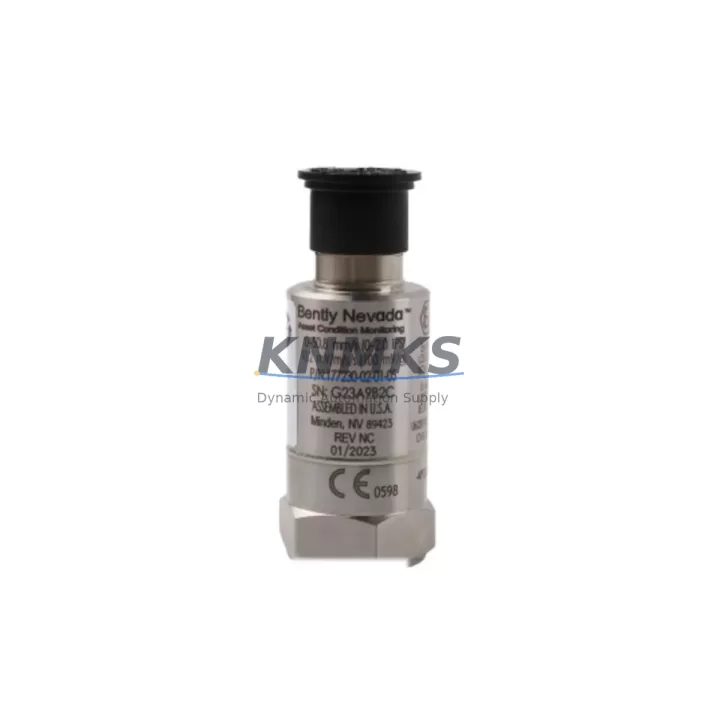
Bently Nevada 177230-01-02-05 Maintenance-Proven Spare Part for Factory Uptime
The Bently Nevada 177230-01-02-05 is a seismic velocity transmitter module designed for the 3500 Series machinery protection system — one of the most widely deployed vibration monitoring platforms in rotating equipment environments worldwide. Whether you are managing a planned annual overhaul, responding to an unplanned trip event, or building a strategic spare parts inventory for a critical compressor train or turbine skid, this module delivers the measurement accuracy and system compatibility required to restore protection coverage without delay.
Sourced as an original spare, each unit undergoes pre-shipment functional verification to confirm signal output integrity, channel isolation, and rack communication before dispatch. With a support terms confirmed by quotation and confirmed long-term supply availability, this module supports both emergency replacement and proactive stock replenishment strategies for maintenance and reliability engineering teams.
Spare Maintenance Table
| Parameter | Specification |
|---|---|
| Part Number | 177230-01-02-05 |
| Brand | Bently Nevada |
| Series | 3500 Series Machinery Protection System |
| Module Type | Seismic Velocity Transmitter Module |
| Rack Compatibility | 3500 Series 19-slot and 4-slot rack configurations |
| Input Signal | Seismic velocity transducer (velocity sensor, geophone) |
| Output | 4–20 mA analog, OK relay, alert/danger relay outputs |
| Measurement Range | Configurable per channel via Rack Configuration Software |
| Power Supply | Supplied via 3500 rack backplane (3500/15 Power Supply Module) |
| Communication | Rack backplane bus; compatible with 3500/92 Communication Gateway |
| Operating Temperature | 0°C to +65°C (32°F to 149°F) |
| Mounting | Direct rack slot insertion, no external wiring adapter required |
| Application Environment | Turbines, compressors, pumps, fans, gearboxes, motor-driven equipment |
| Maintenance Recommendation | Replace on alarm-to-trip escalation, channel drift, or scheduled 3–5 year overhaul cycle |
| Origin | United States |
| Support terms | 12 Months |
| Pre-Shipment Test | Functional verification completed before dispatch |
| Supply Availability | Long-term stock maintained for ongoing procurement |
Maintenance Planning for Continuous Operation
When replacing the 177230-01-02-05 seismic velocity transmitter module in a 3500 Series rack, a thorough site inspection of the surrounding protection system is essential to prevent repeat failures and ensure full protection coverage is restored. Maintenance engineers should begin by verifying the condition of the 3500/15 Power Supply Module, which feeds the entire rack backplane — a degraded or undersized power supply is a common root cause of intermittent channel faults that are incorrectly attributed to the transmitter module itself.
The 3500/20 Rack Interface Module (RIM) should be inspected for firmware currency and communication integrity, as it governs the data exchange between the protection rack and the plant DCS or historian. If the site uses a 3500/92 Communication Gateway Module for Modbus or Ethernet/IP integration, verify that the gateway configuration reflects the updated channel assignments after module replacement.
Seismic velocity transducers — typically geophone-type sensors mounted on bearing housings or equipment casings — should be inspected for cable continuity, connector corrosion, and mounting torque. A faulty transducer will produce erratic readings even with a correctly functioning 177230-01-02-05 module installed. Spare transducer cables and field-mount junction boxes should be included in the site spare parts kit alongside this module.
For sites running mixed vibration and position monitoring, the adjacent 3500/40M Proximitor/Seismic Monitor Module should be checked for channel cross-talk and alarm setpoint integrity. Terminal blocks and field wiring terminations within the control cabinet should be inspected for loose connections, insulation degradation, and correct labeling before the replacement module is commissioned. Where signal isolation is required between the protection system and the DCS analog input cards, confirm that any installed signal isolators or barriers are within calibration and rated for the 4–20 mA loop impedance of the new module.
Finally, if the 3500 rack is installed in a cabinet shared with relay output panels or motor control interfaces, verify that the OK relay and alert/danger relay wiring from the 177230-01-02-05 module is correctly terminated and that downstream relay logic has not been altered during the fault investigation period. A complete loop test — from transducer input through to DCS alarm annunciation — should be performed and documented before returning the equipment to service.
Site Replacement Workflow
Step 1 — Isolation and Permit: Obtain a work permit and confirm that the machinery protection system bypass procedure is in place. Notify the control room that the affected channel will be temporarily out of service. Do not remove the module while the equipment is running without an approved bypass in effect.
Step 2 — Module Removal: Power down the rack slot if the system supports hot-swap inhibit, or follow the site-specific bypass procedure. Carefully extract the 177230-01-02-05 module from the rack slot, noting the slot position and any channel configuration labels on the front panel.
Step 3 — Configuration Backup: Before installing the replacement module, use Bently Nevada Rack Configuration Software to export the current rack configuration file. This ensures that channel setpoints, full-scale ranges, and relay logic are preserved and can be reloaded to the new module without manual re-entry.
Step 4 — Module Installation: Insert the replacement 177230-01-02-05 into the correct rack slot. Confirm that the module is fully seated and that the front panel locking mechanism is engaged. Reload the saved configuration file and verify that all channel parameters are correctly applied.
Step 5 — Loop Verification: Apply a known velocity signal at the transducer input and confirm that the module output, OK relay status, and DCS display all respond correctly. Check alert and danger setpoints against the equipment protection philosophy document.
Step 6 — Return to Service: Remove the bypass, restore normal monitoring, and document the replacement in the site maintenance management system (CMMS). Update the spare parts inventory to reflect the consumed unit and initiate a replenishment order to maintain minimum stock levels.
Spare Parts Support FAQ
Q1: Is the 177230-01-02-05 compatible with all 3500 Series rack configurations?
The 177230-01-02-05 is designed for the Bently Nevada 3500 Series machinery protection platform and is compatible with standard 19-slot and 4-slot rack configurations. Slot compatibility and channel assignment should be verified against the site rack layout drawing and the Rack Configuration Software before installation. If your rack uses an older backplane revision, contact our technical team to confirm compatibility before ordering.
Q2: What pre-shipment testing is performed on each unit?
Each 177230-01-02-05 module undergoes functional verification prior to dispatch, including signal output confirmation, channel isolation check, and backplane communication test. A test record is available upon request. Units are packaged in anti-static protective packaging to prevent ESD damage during transit.
Q3: How should this module be managed within a long-term spare parts strategy?
For critical rotating equipment applications — turbines, compressors, and large pumps — we recommend maintaining a minimum of one spare 177230-01-02-05 module per protection rack on site. Given the 3500 Series platform’s widespread deployment and long service life, long-term supply is maintained to support both emergency replacement and scheduled overhaul cycles. A support terms confirmed by quotation applies from the date of shipment.
Q4: Can this module replace older or discontinued Bently Nevada seismic transmitter variants?
The 177230-01-02-05 is a current-production spare for the 3500 Series seismic velocity monitoring function. For sites migrating from earlier Bently Nevada monitor generations, configuration and wiring compatibility should be reviewed against the original system documentation. Our team can assist with cross-reference verification and migration planning to minimize downtime during the transition.
—
© 2026 KNMKS. All rights reserved.
Original Source: https://knmks.com
Contact: admin@knmks.com | +86 18359268345
Product Identification
- Brand / Ecosystem
-
Bently Nevada
Bently Nevada - Model / Series
-
177230-01-02-05
3500 Series - Product Family
- PLCs & Controllers
- Availability Status
- Available on request after model and quantity confirmation
- Inquiry Type
- B2B RFQ, replacement inquiry and project spare-part request
- Pre-Quote Check
- Exact SKU, brand, series, quantity, nameplate photos and destination country are checked before quotation
System Path
Where this product fits in the KNMKS automation structure.
Specification & Inquiry Focus
- Control platform
- PLC, PAC and modular controllers
- Common needs
- CPU, rack, power and I/O expansion
- Project support
- Replacement, cabinet build and maintenance
Buyer Confirmation
Information KNMKS checks before replying.
- Exact model
- 177230-01-02-05
- Brand / ecosystem
- Bently Nevada
- Product family
- PLCs & Controllers
- Application note
- Replacement, maintenance, project build or spare-part list
- Useful photos
- Nameplate, installed unit, cabinet layout or connector side
- Delivery details
- Quantity, destination country and target schedule
Document Support
Files and notes can be confirmed during quotation.
- Product photos or nameplate confirmation when available
- Packing and delivery notes before quotation confirmation
- Support scope and delivery terms confirmed per inquiry
- Export document coordination for qualified B2B requests
Inquiry Support
- Model cross-checking before quotation
- CPU, power, rack and expansion module matching
- Support for replacement and project inquiry
What to Send Us
- Brand and exact model number: Bently Nevada 177230-01-02-05
- Quantity and required delivery time
- Application, replacement requirement or nameplate photo
- Destination country and shipping preference
RFQ Preparation
This is a product inquiry page built for RFQ communication.
Fast Model Check
Send this model to KNMKS for confirmation.
Include quantity, destination country and photos if this is a maintenance replacement. The inquiry will be saved with a reference number after submission.
Brand & Compatibility Note
KNMKS displays automation product information for well-known industrial brand ecosystems and compatible replacement references. Brand names are used for product identification and compatibility reference only; final availability and commercial terms are confirmed per quotation.
 Manufacturing
 Machine Tools
 Packaging
 Energy & Power
 HMI & Displays
 Servo Systems
 Variable Frequency Drives
 Sensors