
Overview
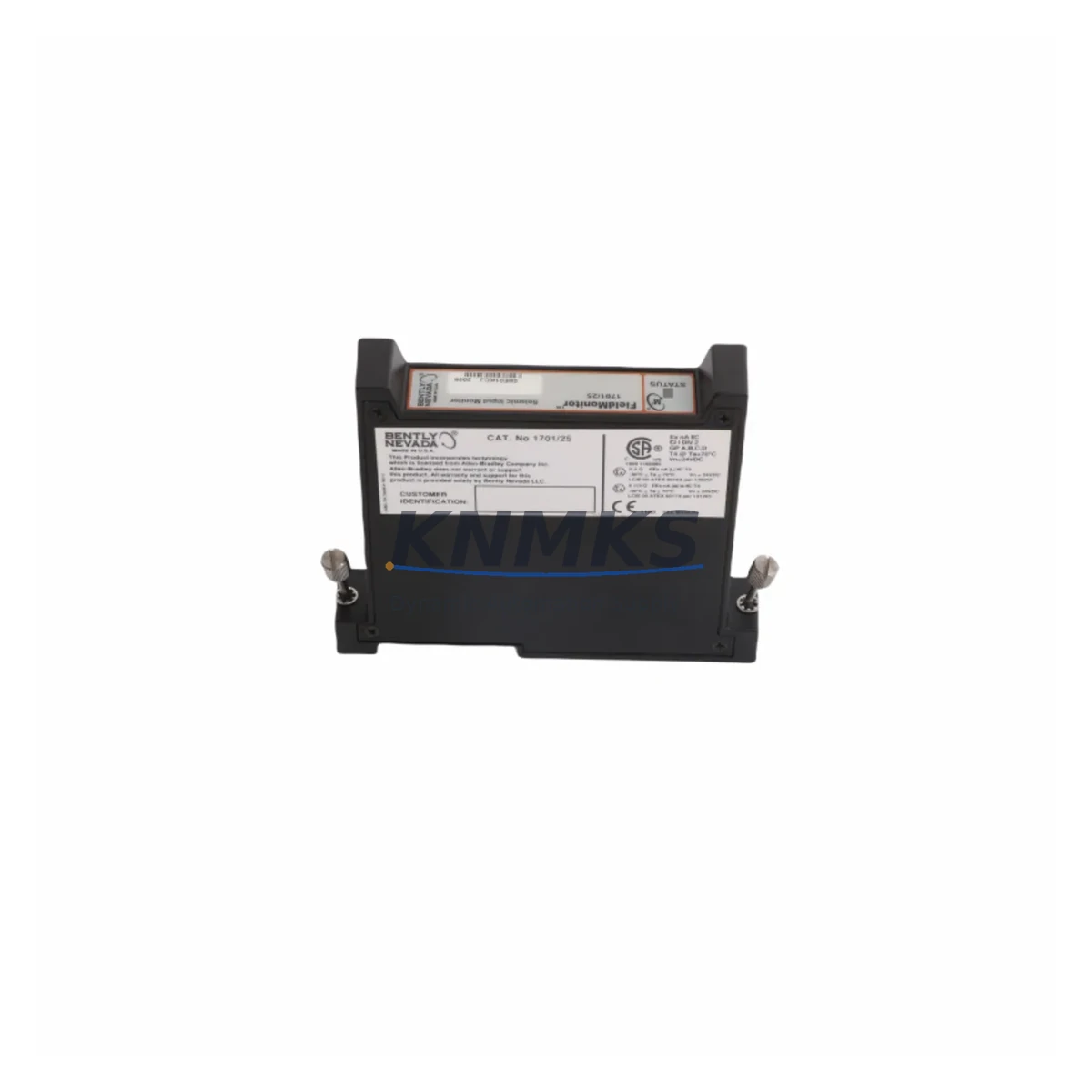
Bently Nevada 1701/25 Migration-Ready Acceleration Input Module: Legacy System Migration and Compatible Upgrade
The Bently Nevada 1701/25 Acceleration Input Module is a critical component within the 1701 Series Condition Monitoring System (CMS), designed to acquire high-frequency vibration signals from accelerometers mounted on rotating machinery such as compressors, turbines, pumps, and fans. As legacy 1701 CMS installations approach end-of-support milestones, plant engineers and reliability teams face increasing pressure to source verified replacement modules that maintain signal fidelity, rack compatibility, and software integration without triggering a full system overhaul.
This migration-ready 1701/25 module is sourced from verified supply channels, pre-shipment tested against OEM functional specifications, and backed by a support terms confirmed by quotation. It is suitable for direct slot replacement within existing 1701 Series racks, supporting continuity of condition monitoring programs during planned maintenance windows or emergency spare deployment.
Migration Compatibility Table
| Parameter | Details |
|---|---|
| SKU / Part Number | 1701/25 |
| Brand / OEM | Bently Nevada |
| Series | 1701 Condition Monitoring System (CMS) |
| Module Function | Acceleration Input — acquires vibration data from ICP/IEPE accelerometers |
| Rack / Backplane Compatibility | 1701 Series rack; standard 1701 backplane slot interface |
| Signal Input Type | Accelerometer (ICP/IEPE), high-frequency vibration |
| Communication Interface | Internal 1701 CMS backplane bus; compatible with System 1 software |
| Replacement Scope | Direct slot-for-slot replacement of existing 1701/25 modules |
| Installation Space | Standard 1701 rack slot — no mechanical modification required |
| Firmware Compatibility | Compatible with existing 1701 CMS firmware revisions; verify rack firmware version prior to installation |
| Commissioning Notes | Confirm channel address assignment, accelerometer sensitivity scaling, and alarm setpoints in System 1 configuration |
| Pre-Shipment Testing | Functional test performed against OEM specifications before dispatch |
| Support terms | 12 Months |
| Dispatch | Global — rapid dispatch from verified stock |
Retrofit Planning for Existing Automation Systems
Replacing a 1701/25 Acceleration Input Module within an operational 1701 CMS installation requires careful pre-work to avoid disrupting the broader condition monitoring architecture. Before removing the existing module, engineers should document the current channel configuration within System 1 software, including measurement point assignments, transducer sensitivity values (typically expressed in mV/g), full-scale ranges, and alarm/danger setpoints. These parameters must be re-entered or verified after the replacement module is seated in the rack.
The 1701 Series rack backplane distributes power and communication to all installed modules. When planning a 1701/25 swap, confirm that the 1701/15 Power Supply Module supplying the rack is operating within its rated output capacity — adding or replacing input modules can affect total rack power draw. If the rack also houses a 1701/05 Communication Gateway Module, verify that the gateway firmware version is compatible with the replacement module’s expected behavior on the backplane bus.
For installations where the 1701 CMS feeds vibration data to a DCS or safety system via a 1701/40 Relay Output Module or a 1701/50 Ethernet Communication Module, confirm that the data path from the new acceleration input channel through to the relay or network output remains intact after replacement. In some configurations, channel-to-relay mapping must be re-validated in System 1 following a module swap.
Where the existing installation includes a 3500/42M Proximitor/Seismic Monitor or other 3500 Series modules in adjacent racks sharing the same System 1 server, ensure that the 1701 CMS rack’s communication link to the server is not interrupted during the replacement procedure. Coordinate with the control room to place affected measurement points in bypass or inhibit mode within System 1 before pulling the module, preventing spurious alarms from propagating to the DCS or historian.
If the retrofit scope extends to replacing multiple 1701/25 modules across a rack, consider sequencing replacements channel by channel during a planned shutdown window rather than pulling all modules simultaneously. This approach preserves partial monitoring coverage and reduces the risk of losing vibration trend data for critical machinery during the transition period.
Downtime Control During System Migration
Minimizing unplanned downtime during a 1701/25 module replacement begins with preparation. Before the maintenance window opens, obtain a full export of the System 1 configuration database for the affected rack. This backup preserves all measurement point definitions, alarm logic, trend configurations, and communication settings, enabling rapid restoration if the replacement module requires re-commissioning from scratch.
During the swap, place the affected measurement channels in inhibit mode within System 1 to suppress alarm outputs to the DCS and prevent false trips. If the plant operates under a safety instrumented system (SIS) that receives inputs from the 1701 CMS, coordinate with the SIS engineer to confirm that the inhibit state is recognized and that the SIS logic does not interpret the loss of the vibration signal as a fault condition requiring a protective action.
Once the replacement 1701/25 is seated and the rack is powered, allow the module to complete its self-test sequence before re-enabling the measurement channels. Verify live signal readings against known baseline values from the accelerometers — a significant deviation may indicate a wiring issue at the terminal block, an incorrect sensitivity scaling entry, or a transducer fault unrelated to the module replacement. Confirm that System 1 is receiving and logging data from the new module before removing the inhibit flags and returning the channels to normal monitoring status.
For sites with strict change management requirements, document the replacement with before-and-after screenshots of the System 1 channel configuration, the module serial number, and the functional test results. This record supports audit readiness and provides a reference baseline for future maintenance cycles.
Retrofit Support FAQ
Q1: Is the 1701/25 a direct replacement for the existing module in my 1701 Series rack?
Yes. The 1701/25 is designed for slot-for-slot installation in the 1701 Series rack backplane. No mechanical modification to the rack or cabinet is required. After seating the module, verify channel address assignments and transducer sensitivity settings in System 1 to confirm correct operation.
Q2: What wiring checks should I perform before and after replacing the 1701/25?
Inspect the terminal block connections for the accelerometer signal cables — confirm correct polarity, shield grounding, and cable continuity. ICP/IEPE accelerometers require a constant-current excitation supply from the input module; verify that the replacement module’s excitation output is within the accelerometer’s specified operating range. Re-torque terminal screws to the specified value after reconnection.
Q3: How do I confirm compatibility between the replacement 1701/25 and my current System 1 software version?
Check the System 1 software release notes for the firmware revision installed on your 1701 CMS rack. The 1701/25 is compatible with the standard 1701 Series firmware baseline; however, if your rack is running a customized or site-specific firmware build, contact your system integrator to confirm compatibility before installation. Our pre-shipment test report documents the firmware environment used during functional verification.
Q4: What does the support terms confirmed by quotation cover, and how is stock availability managed?
The support terms confirmed by quotation cover functional defects identified under normal operating conditions consistent with the 1701 CMS application environment. Each unit is pre-shipment tested against OEM functional specifications prior to dispatch. Stock is maintained across multiple locations to support rapid global dispatch for both planned maintenance and emergency replacement scenarios. Contact admin@knmks.com or +86 18359268345 to confirm current availability and lead time.
© 2026 KNMKS. All rights reserved.
Original Source: https://knmks.com
Contact: admin@knmks.com | +86 18359268345
Product Identification
- Brand / Ecosystem
-
Bently Nevada
Bently Nevada - Model / Series
- 1701/25
- Product Family
- PLCs & Controllers
- Availability Status
- Available on request after model and quantity confirmation
- Inquiry Type
- B2B RFQ, replacement inquiry and project spare-part request
- Pre-Quote Check
- Exact SKU, brand, series, quantity, nameplate photos and destination country are checked before quotation
System Path
Where this product fits in the KNMKS automation structure.
Specification & Inquiry Focus
- Control platform
- PLC, PAC and modular controllers
- Common needs
- CPU, rack, power and I/O expansion
- Project support
- Replacement, cabinet build and maintenance
Buyer Confirmation
Information KNMKS checks before replying.
- Exact model
- 1701/25
- Brand / ecosystem
- Bently Nevada
- Product family
- PLCs & Controllers
- Application note
- Replacement, maintenance, project build or spare-part list
- Useful photos
- Nameplate, installed unit, cabinet layout or connector side
- Delivery details
- Quantity, destination country and target schedule
Document Support
Files and notes can be confirmed during quotation.
- Product photos or nameplate confirmation when available
- Packing and delivery notes before quotation confirmation
- Support scope and delivery terms confirmed per inquiry
- Export document coordination for qualified B2B requests
Inquiry Support
- Model cross-checking before quotation
- CPU, power, rack and expansion module matching
- Support for replacement and project inquiry
What to Send Us
- Brand and exact model number: Bently Nevada 1701/25
- Quantity and required delivery time
- Application, replacement requirement or nameplate photo
- Destination country and shipping preference
RFQ Preparation
This is a product inquiry page built for RFQ communication.
Fast Model Check
Send this model to KNMKS for confirmation.
Include quantity, destination country and photos if this is a maintenance replacement. The inquiry will be saved with a reference number after submission.
Brand & Compatibility Note
KNMKS displays automation product information for well-known industrial brand ecosystems and compatible replacement references. Brand names are used for product identification and compatibility reference only; final availability and commercial terms are confirmed per quotation.
 Manufacturing
 Machine Tools
 Packaging
 Energy & Power
 HMI & Displays
 Servo Systems
 Variable Frequency Drives
 Sensors