
Overview
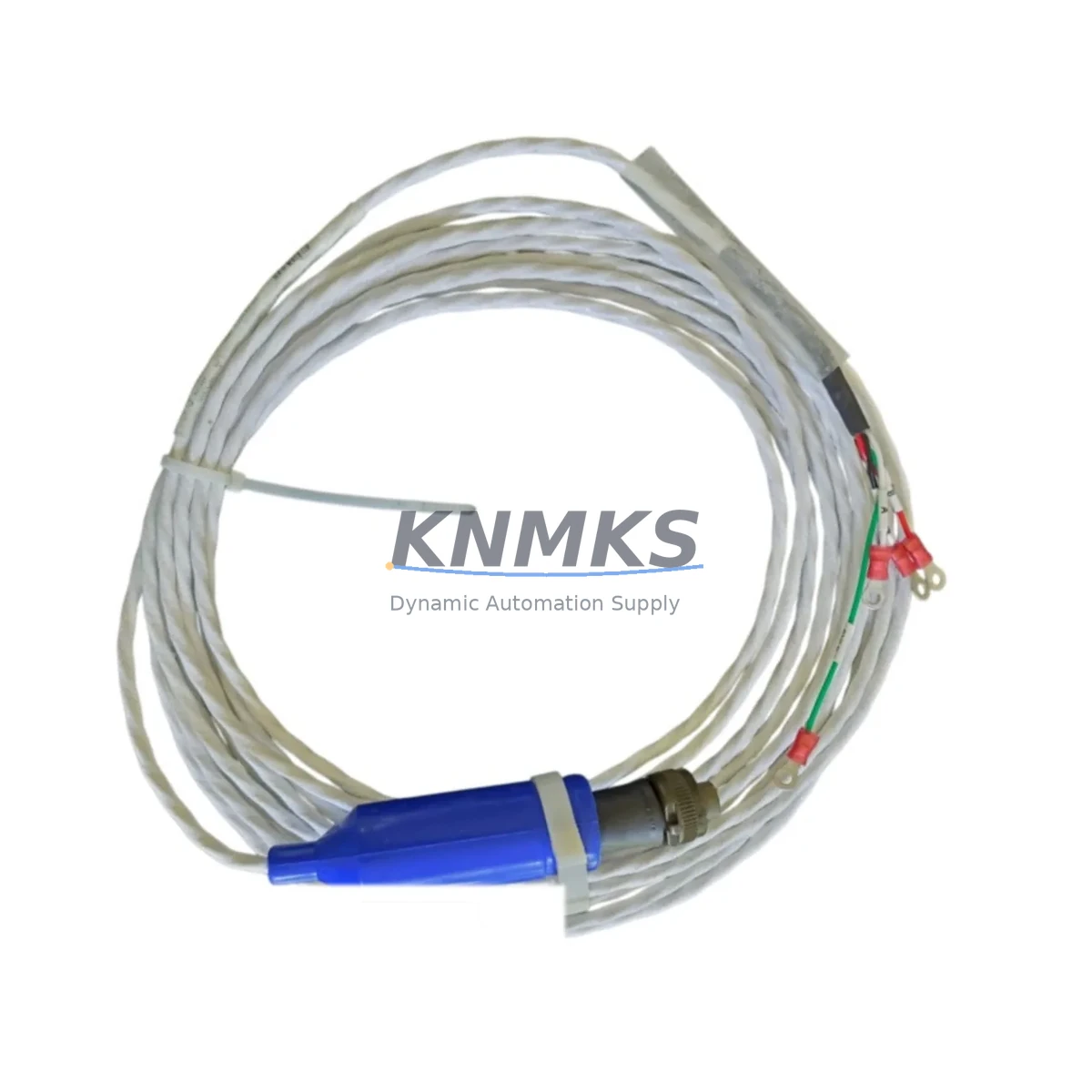
Bently Nevada 130539-15 Interconnect Cable 3500 Spare: Maintenance-Proven Spare Part for Factory Uptime
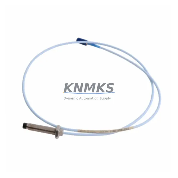
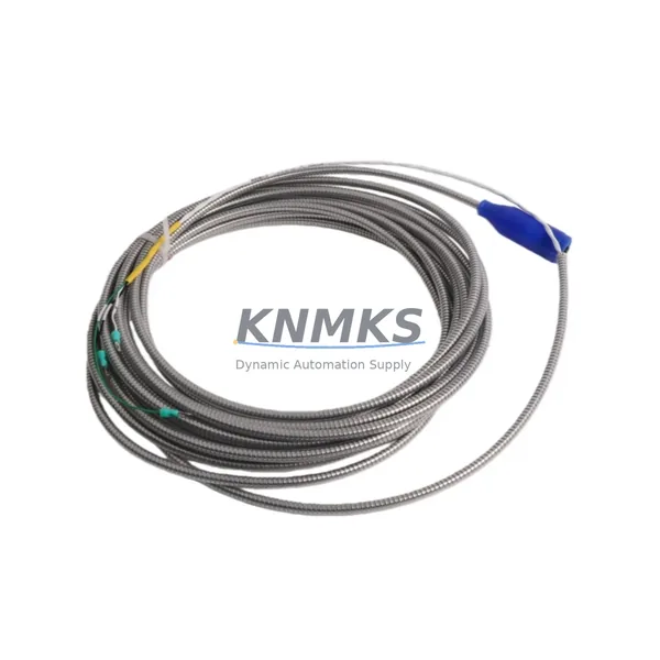
The Bently Nevada 130539-15 is an original interconnect cable engineered for the 3500 Series Machinery Protection System — one of the most widely deployed vibration monitoring and machinery protection platforms in rotating equipment environments worldwide. Whether you are managing a gas turbine train, a centrifugal compressor, a steam turbine, or a large pump set, the 130539-15 interconnect cable is a critical signal path component that links field-mounted transducers to the 3500 rack’s I/O and monitor modules. Maintaining a verified spare of this cable in your site inventory is a fundamental requirement for any maintenance team committed to minimizing unplanned downtime and sustaining continuous plant operation.
This spare part is sourced as an original Bently Nevada component, fully tested prior to shipment, and backed by a support terms confirmed by quotation. It is suitable for direct replacement in existing 3500 Series installations without requiring firmware changes, rack reconfiguration, or additional calibration — provided the replacement is performed according to Bently Nevada’s field installation procedures.
Spare Maintenance Table
| Parameter | Specification / Detail |
|---|---|
| Part Number / SKU | 130539-15 |
| Brand | Bently Nevada |
| Series Compatibility | 3500 Series Machinery Protection System |
| Product Type | Interconnect Cable |
| Application | Signal interconnection between transducers and 3500 rack monitor/I/O modules |
| Typical Installation Environment | Industrial plant rooms, turbine control cabinets, compressor skids, rotating equipment monitoring panels |
| Origin | United States |
| Weight | 620 g |
| Compatibility Verification | Verified for 3500 Series rack architecture; confirm rack slot and module type before installation |
| Replacement Scope | Direct drop-in replacement for failed or degraded 130539-15 cables in existing installations |
| Pre-Shipment Testing | Continuity, insulation resistance, and connector integrity tested before dispatch |
| Support terms | 12 Months from date of shipment |
| Lead Time | availability confirmed by RFQ — typically ships within 2–5 business days |
| Long-Term Supply | Committed long-term sourcing; suitable for annual maintenance contracts and multi-site procurement |
Maintenance Planning for Continuous Operation
For maintenance engineers managing 3500 Series installations, the 130539-15 interconnect cable should never be treated as a standalone component. Its failure — whether due to connector wear, cable fatigue from vibration, insulation degradation in high-temperature environments, or physical damage during routine cabinet access — can interrupt the signal chain between your proximity probes or velocity transducers and the 3500 monitor modules, triggering spurious trips or, worse, masking genuine machinery faults.
When planning a replacement of the 130539-15, a thorough site inspection should extend to the adjacent components in the same signal loop and control cabinet. The 3500/20 Rack Interface Module and the relevant 3500/40M or 3500/42M Proximitor/Seismic Monitor modules should be inspected for connector pin condition and any signs of corrosion or intermittent contact. The 3500/15 Power Supply Module should be checked for output voltage stability, as a marginal power supply can accelerate cable connector wear and introduce noise into vibration signals.
Field wiring terminations at the 3500 I/O module terminal blocks and any associated junction boxes or field terminal assemblies (FTAs) should be inspected for loose connections, moisture ingress, and correct torque. If your installation uses signal isolators or signal conditioners between the transducer output and the rack input, these should be verified for correct gain and offset settings following any cable replacement. In installations where the 3500 rack communicates with a DCS or SCADA system via Modbus or OPC-DA/UA communication modules, confirm that the communication link remains stable after the cable swap and that no alarm or trip setpoints have been inadvertently altered.
Procurement engineers should note that the 130539-15 is a high-demand spare across petrochemical, power generation, and LNG facilities. Maintaining a minimum stock of two units per rack installation — with annual replenishment aligned to your site’s planned shutdown schedule — is a widely adopted best practice. Pairing this cable spare with a stocked 3500/22M Transient Data Interface module and a set of 330130 or 330180 Series proximity probes ensures that your team can address the most common signal-path failure modes without waiting on international procurement lead times.
Site Replacement Workflow
Replacing the 130539-15 interconnect cable in a live 3500 Series installation requires a structured approach to avoid introducing new faults or triggering unnecessary machinery trips. The following workflow reflects standard field practice for maintenance teams operating under a planned or emergency replacement scenario:
1. Pre-Replacement Verification: Confirm the replacement cable’s part number (130539-15) matches the installed cable. Inspect the new cable’s connectors for shipping damage and verify continuity with a calibrated multimeter before bringing it to the field. Cross-reference the 3500 rack’s channel assignment documentation to confirm which monitor module and I/O slot the cable serves.
2. Bypass and Isolation: Where plant operating procedures permit, place the affected monitoring channel in bypass mode via the 3500 rack’s front-panel or software interface to prevent a spurious trip during the cable swap. Notify the control room and document the bypass in your maintenance management system.
3. Cable Removal and Inspection: Disconnect the existing 130539-15 from both the transducer end and the rack module connector. Inspect the vacated connectors on the monitor module and the field junction for pin damage, corrosion, or debris. Clean connector bodies with approved contact cleaner if required.
4. Installation and Routing: Route the new 130539-15 following the original cable path, maintaining adequate separation from high-voltage power cables and sources of electromagnetic interference. Secure the cable with appropriate cable ties or clamps to prevent vibration-induced fatigue at the connector terminations.
5. Post-Installation Verification: Remove the channel bypass, observe the live vibration or position readings on the 3500 monitor, and confirm that signal levels are within expected ranges for the machine’s current operating condition. Compare readings against historical baseline data where available. Document the replacement in your CMMS with the new cable’s serial number and installation date.
This workflow applies equally to planned annual maintenance replacements and to emergency field swaps following an unplanned cable failure. The 130539-15’s direct-replacement compatibility with existing 3500 Series installations means that no rack reconfiguration or software changes are required, significantly reducing the time-to-restore for affected monitoring channels.
Spare Parts Support FAQ
Q1: Is the 130539-15 compatible with all 3500 Series monitor modules?
The 130539-15 is designed for use within the 3500 Series rack architecture. Compatibility depends on the specific monitor module type and rack slot assignment in your installation. Before ordering, confirm the module part number (e.g., 3500/40M, 3500/42M, 3500/44M) and the cable routing requirements for your specific rack configuration. Our technical team can assist with compatibility verification based on your rack layout documentation.
Q2: What pre-shipment testing is performed on the 130539-15?
Every 130539-15 unit is tested for electrical continuity across all conductors, insulation resistance between conductors and shield, and mechanical integrity of both connector assemblies before dispatch. A test record is available upon request. Units that do not meet specification are not shipped.
Q3: Can you support long-term or blanket purchase orders for the 130539-15?
Yes. We support annual maintenance contracts, blanket purchase orders, and multi-site procurement agreements for the 130539-15 and related 3500 Series spare parts. Long-term supply commitments allow your procurement team to lock in pricing and ensure stock availability aligned to your planned maintenance schedule. Contact our sales team to discuss terms.
Q4: What does the support terms confirmed by quotation cover?
The support terms confirmed by quotation cover manufacturing defects, connector failures, and electrical performance issues arising under normal operating conditions. It does not cover damage resulting from incorrect installation, physical abuse, or use outside the specified environmental parameters. Support requests are processed with a replacement unit dispatched after fault verification. The confirmed support period begins from the date of shipment.
© 2026 KNMKS. All rights reserved.
Original Source: https://knmks.com
Contact: admin@knmks.com | +86 18359268345
Product Identification
- Brand / Ecosystem
-
Bently Nevada
Bently Nevada - Model / Series
-
130539-15
3500 Series - Product Family
- Cables & Connectors
- Availability Status
- Available on request after model and quantity confirmation
- Inquiry Type
- B2B RFQ, replacement inquiry and project spare-part request
- Pre-Quote Check
- Exact SKU, brand, series, quantity, nameplate photos and destination country are checked before quotation
System Path
Where this product fits in the KNMKS automation structure.
Specification & Inquiry Focus
- Cable range
- Sensor, servo, network and circular connectors
- Common needs
- Length, pin count, shielding and plug type
- Project support
- Machine wiring and installation kits
Buyer Confirmation
Information KNMKS checks before replying.
- Exact model
- 130539-15
- Brand / ecosystem
- Bently Nevada
- Product family
- Cables & Connectors
- Application note
- Replacement, maintenance, project build or spare-part list
- Useful photos
- Nameplate, installed unit, cabinet layout or connector side
- Delivery details
- Quantity, destination country and target schedule
Document Support
Files and notes can be confirmed during quotation.
- Product photos or nameplate confirmation when available
- Packing and delivery notes before quotation confirmation
- Support scope and delivery terms confirmed per inquiry
- Export document coordination for qualified B2B requests
Inquiry Support
- Cable length and connector type confirmation
- Servo, sensor and network cable inquiry
- Accessory kits for installation teams
What to Send Us
- Brand and exact model number: Bently Nevada 130539-15
- Quantity and required delivery time
- Application, replacement requirement or nameplate photo
- Destination country and shipping preference
RFQ Preparation
This is a product inquiry page built for RFQ communication.
Fast Model Check
Send this model to KNMKS for confirmation.
Include quantity, destination country and photos if this is a maintenance replacement. The inquiry will be saved with a reference number after submission.
Brand & Compatibility Note
KNMKS displays automation product information for well-known industrial brand ecosystems and compatible replacement references. Brand names are used for product identification and compatibility reference only; final availability and commercial terms are confirmed per quotation.
 Manufacturing
 Machine Tools
 Packaging
 Energy & Power
 PLCs & Controllers
 HMI & Displays
 Servo Systems
 Variable Frequency Drives