
Overview
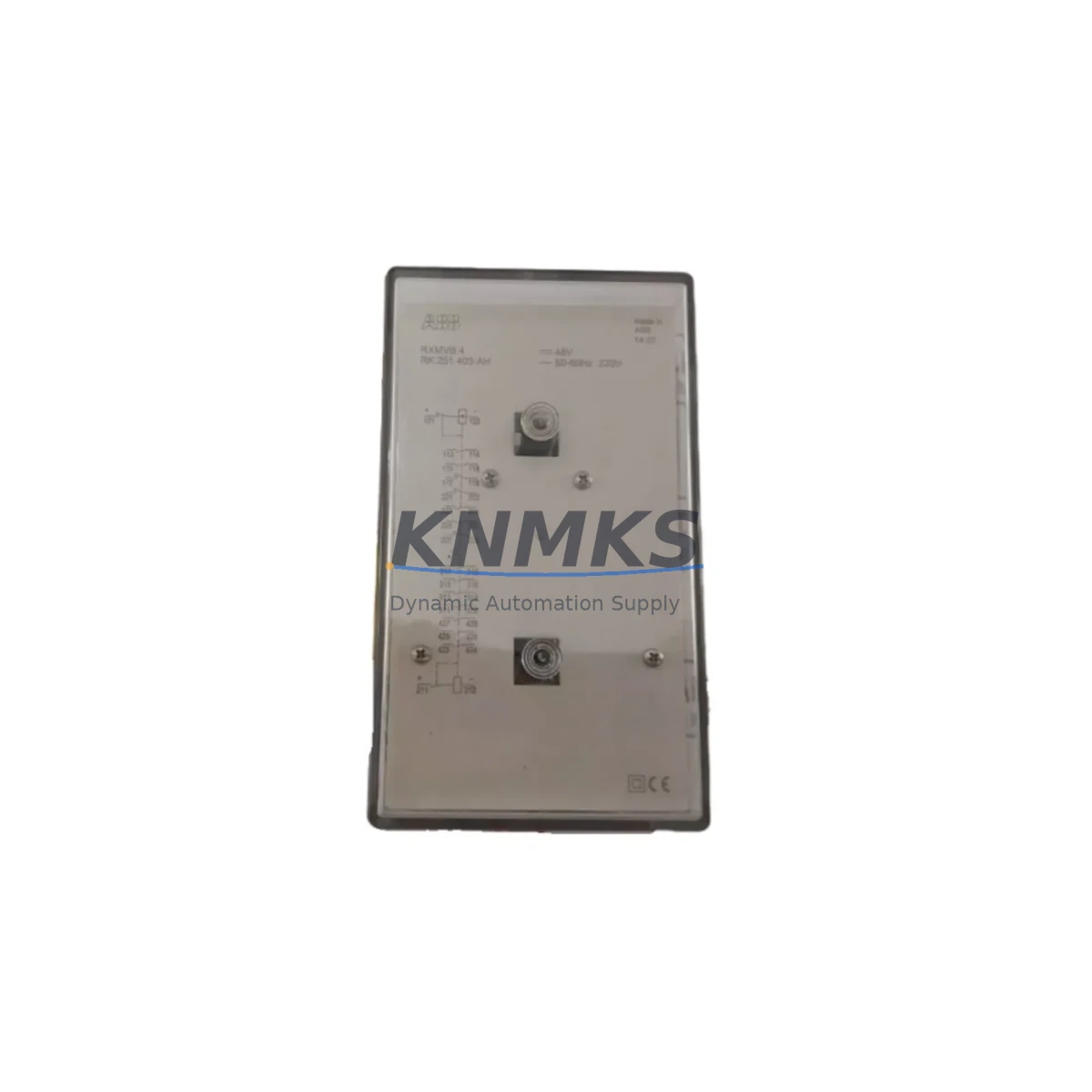
ABB RXMVB4 Migration-Ready Bistable Relay for Legacy Control Systems
The ABB RXMVB4 is a migration-ready bistable (latching) relay engineered as a direct plug-in replacement for discontinued RXMV Series relays widely deployed in legacy industrial control panels, motor control centers, and PLC-driven automation cabinets. As aging RXMV-family components reach end-of-life and OEM spare-part pipelines dry up, the RXMVB4 provides a verified, drop-in upgrade path that preserves existing wiring harnesses, terminal block layouts, and relay socket footprints — dramatically reducing retrofit labor and unplanned downtime.
Designed for 4-contact plug-in mounting, the RXMVB4 retains the bistable (mechanically latched) switching characteristic that makes it indispensable in fail-safe interlocking circuits, emergency-stop loops, and energy-saving hold circuits where coil power must not be continuously applied. Its dual-coil set/reset architecture is fully compatible with the relay output modules of Siemens S5/S7 series PLCs, ABB AC500 controllers, and Schneider Electric Modicon M340/M580 platforms — making cross-brand panel upgrades straightforward without reprogramming the control logic.
Migration Compatibility Table
| Parameter | Legacy RXMV Series (Discontinued) | ABB RXMVB4 (Replacement) | Migration Note |
|---|---|---|---|
| Contact Configuration | 4-contact plug-in | 4-contact plug-in (4CO) | Direct socket compatibility — no rewiring required |
| Switching Type | Bistable / Latching | Bistable / Latching | Identical logic behavior; no PLC program changes needed |
| Coil Architecture | Dual-coil (Set / Reset) | Dual-coil (Set / Reset) | Verify coil voltage rating matches existing wiring |
| Mounting / Socket | RXZE2M4 / RXZE1M4 socket | RXZE2M4 / RXZE1M4 compatible | Confirm socket model on panel before ordering |
| Communication Protocol | Hardwired relay output | Hardwired relay output | No protocol migration required; integrates with any PLC DO module |
| Installation Space | Standard DIN-rail relay footprint | Identical footprint | No panel cutout modification needed |
| Firmware / Software | N/A (hardwired) | N/A (hardwired) | No firmware update or driver installation required |
| Commissioning | Manual set/reset pulse test | Manual set/reset pulse test | Verify latch state with multimeter before energizing load circuit |
| Support terms | OEM support terms expired (EOL) | support terms confirmed by quotation | Covered from date of shipment; includes functional test certificate |
Retrofit Planning for Existing Automation Systems
A successful RXMVB4 retrofit begins well before the relay is physically swapped. Maintenance engineers should first audit the existing control cabinet to confirm the installed relay socket model — typically an ABB RXZE2M4 or RXZE1M4 — since the RXMVB4 is designed to seat directly into these sockets without modification. If the socket itself shows signs of contact wear or arc erosion from years of switching duty, replacing the socket alongside the relay eliminates a common root cause of intermittent faults after installation.
Power supply capacity is the next critical checkpoint. Bistable relays draw current only during the set or reset pulse, but the upstream 24 VDC power supply module — often a shared rail feeding multiple relay outputs, solenoid valves, and indicator lamps — must be verified to handle the inrush current of simultaneous switching events during startup sequences. If the existing PSU is already running near its rated output, adding a dedicated secondary rail for the relay coil circuit is strongly recommended before commissioning the replacement.
Terminal block wiring should be documented with photographs and a point-to-point continuity check before any relay is removed. In legacy panels built to IEC 60204-1, the set coil (A1/A2) and reset coil (B1/B2) terminals are often color-coded, but decades of field modifications can introduce non-standard wiring. Cross-referencing the as-built wiring diagram against the actual terminal connections prevents miswiring the RXMVB4’s dual-coil inputs — a mistake that can damage the relay output card of the connected PLC or ABB AC500 I/O expansion module.
For systems where the RXMVB4 interfaces with a Siemens S7-300 digital output module (such as the SM 322) or a Schneider Electric Modicon TM3 I/O module, the PLC program’s output assignment table should be reviewed to confirm that the set and reset coil addresses map correctly to the replacement relay’s terminal numbering. In most cases, the program logic requires no modification — but the output scan time and pulse width parameters in the function block should be validated to ensure the bistable latch engages reliably under the new relay’s coil inductance characteristics.
Where the legacy system includes an HMI panel — such as an ABB CP600 or Siemens SIMATIC HMI TP700 — the relay status feedback signal (typically a normally-open auxiliary contact wired back to a digital input) should be tested after replacement to confirm that the HMI mimic diagram correctly reflects the RXMVB4’s latched state. This is especially important in interlock and permissive circuits where the HMI operator display is the primary indication of relay position.
Finally, if the retrofit involves multiple relay replacements across a large panel or a multi-cabinet system, a programming cable (such as the ABB USB-to-serial adapter for AC500 or the Siemens PC Adapter USB for S7) should be on-site to allow live monitoring of PLC I/O status during commissioning — enabling engineers to verify each relay’s set/reset response in real time without relying solely on indicator lamps.
Downtime Control During System Migration
Minimizing production downtime during a relay replacement requires a structured hot-swap protocol. Before the maintenance window opens, the RXMVB4 should be pre-tested on a bench fixture that replicates the coil voltage and load circuit of the target installation. Applying the set pulse and reset pulse in sequence — and verifying contact continuity with a calibrated multimeter — confirms the relay is fully functional before it enters the panel. This pre-commissioning step, which takes less than five minutes per unit, eliminates the risk of installing a transit-damaged component and discovering the fault only after the system is re-energized.
During the swap itself, the PLC program should be placed in STOP mode and the relevant output module de-energized before the relay is removed from its socket. This protects the PLC’s output transistors from back-EMF transients and prevents unintended actuation of downstream equipment — particularly critical in systems controlling pneumatic valves, motor starters, or safety interlocks. The original relay’s latch state (set or reset) should be recorded before removal so the RXMVB4 can be pre-positioned to the same state before re-energizing, preserving the control logic continuity that the HMI operator expects to see.
After the RXMVB4 is seated and the panel is re-energized, a structured I/O force test — using the PLC programming software to individually pulse the set and reset outputs — confirms correct wiring and latch behavior before returning the system to automatic mode. Documenting the as-found and as-left relay states, coil voltages measured at the socket terminals, and contact resistance readings provides a baseline for future predictive maintenance and supports the support terms confirmed by quotation claim process if a field failure occurs.
Retrofit Support FAQ
Q1: Is the ABB RXMVB4 a direct replacement for all RXMV Series variants?
The RXMVB4 is the standard 4-contact bistable replacement for the RXMV Series plug-in relay family. It is compatible with RXZE2M4 and RXZE1M4 sockets. If your legacy installation uses a different contact count or socket type, please confirm the exact legacy part number with our technical team before ordering to ensure full dimensional and electrical compatibility.
Q2: Does replacing the RXMVB4 require changes to the PLC program or HMI configuration?
In the vast majority of retrofit applications, no program changes are required. The RXMVB4 replicates the bistable switching behavior of the original RXMV relay, so existing ladder logic, function block diagrams, and HMI tag assignments remain valid. The only verification needed is confirming that the PLC output pulse width is sufficient to reliably latch the RXMVB4 — typically 20–50 ms, which is well within the default output timing of most modern PLC platforms.
Q3: What pre-shipment testing is performed on each RXMVB4 unit?
Every RXMVB4 supplied by KNMKS undergoes a functional test covering coil energization at rated voltage, contact continuity in both latched states, insulation resistance between coil and contact circuits, and mechanical operation verification. A test certificate is available upon request. Units are shipped in anti-static packaging with individual serial tracking to support support terms registration and traceability.
Q4: What does the support terms confirmed by quotation cover, and how is a claim initiated?
The support terms confirmed by quotation cover manufacturing defects, premature contact failure under normal switching duty, and coil open-circuit faults. It does not cover damage resulting from incorrect installation, overvoltage, or mechanical impact. To initiate a support terms claim, contact KNMKS with the unit serial number, purchase order reference, and a description of the failure mode. Replacement units are dispatched within 3 business days of claim approval, with no requirement to return the failed unit for low-value claims.
© 2026 KNMKS. All rights reserved.
Original Source: https://knmks.com
Contact: admin@knmks.com | +86 18359268345
Product Identification
- Brand / Ecosystem
-
ABB
ABB - Model / Series
- RXMVB4
- Product Family
- Relays & Interface
- Availability Status
- Available on request after model and quantity confirmation
- Inquiry Type
- B2B RFQ, replacement inquiry and project spare-part request
- Pre-Quote Check
- Exact SKU, brand, series, quantity, nameplate photos and destination country are checked before quotation
System Path
Where this product fits in the KNMKS automation structure.
Specification & Inquiry Focus
- Interface range
- Relays, isolation and signal modules
- Common needs
- Coil voltage and contact rating
- Project support
- Panel wiring and signal protection
Buyer Confirmation
Information KNMKS checks before replying.
- Exact model
- RXMVB4
- Brand / ecosystem
- ABB
- Product family
- Relays & Interface
- Application note
- Replacement, maintenance, project build or spare-part list
- Useful photos
- Nameplate, installed unit, cabinet layout or connector side
- Delivery details
- Quantity, destination country and target schedule
Document Support
Files and notes can be confirmed during quotation.
- Product photos or nameplate confirmation when available
- Packing and delivery notes before quotation confirmation
- Support scope and delivery terms confirmed per inquiry
- Export document coordination for qualified B2B requests
Inquiry Support
- Relay base and module matching
- Signal isolation and protection options
- Panel accessory inquiry support
What to Send Us
- Brand and exact model number: ABB RXMVB4
- Quantity and required delivery time
- Application, replacement requirement or nameplate photo
- Destination country and shipping preference
RFQ Preparation
This is a product inquiry page built for RFQ communication.
Fast Model Check
Send this model to KNMKS for confirmation.
Include quantity, destination country and photos if this is a maintenance replacement. The inquiry will be saved with a reference number after submission.
Brand & Compatibility Note
KNMKS displays automation product information for well-known industrial brand ecosystems and compatible replacement references. Brand names are used for product identification and compatibility reference only; final availability and commercial terms are confirmed per quotation.
 Manufacturing
 Machine Tools
 Packaging
 Energy & Power
 PLCs & Controllers
 HMI & Displays
 Servo Systems
 Variable Frequency Drives