
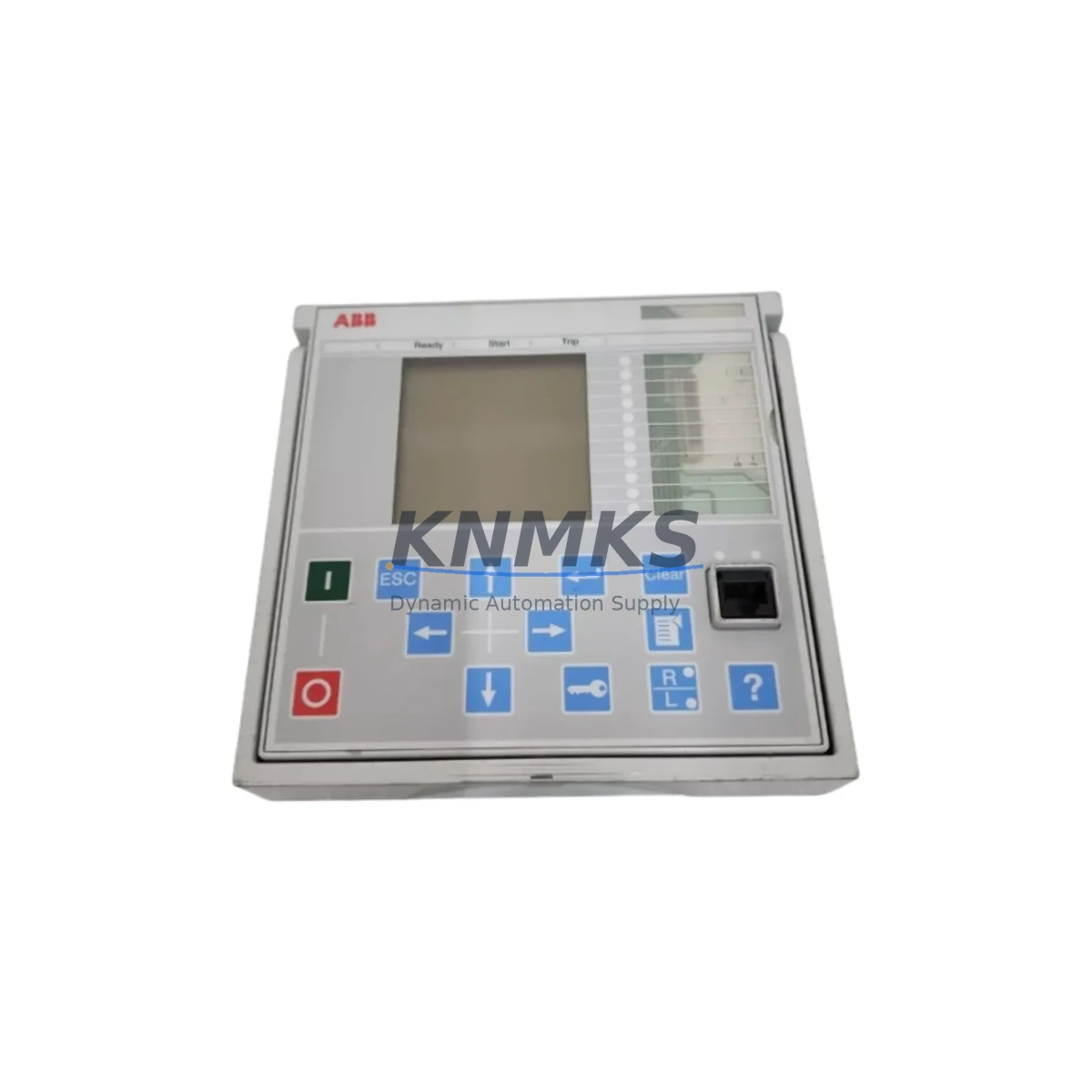
Overview
ABB FER615E-D Migration-Ready Feeder Protection Relay: Legacy System Retrofit & Compatibility Upgrade
The ABB FER615E-D is a feeder protection relay belonging to ABB’s Relion® 615 Series Intelligent Electronic Device (IED) platform — one of the most widely deployed protection families in medium-voltage distribution networks worldwide. As aging SPAJ, SPAC, and REF541/REF543 generation relays approach end-of-life, the FER615E-D has become a primary migration target for utilities, industrial plant operators, and EPC contractors executing systematic protection panel upgrades. Its compact 4U chassis, dual-port IEC 61850 GOOSE communication, and configurable I/O architecture make it a technically sound and commercially available replacement for a broad range of legacy feeder protection devices.
Whether you are managing a substation modernization program, responding to an OEM discontinuation notice, or sourcing a critical spare to restore a tripped feeder bay, the FER615E-D offers a verified migration path with in-stock availability, pre-shipment functional testing, and a support terms confirmed by quotation covering both hardware and firmware integrity.
Migration Compatibility Table
| Parameter | FER615E-D Specification | Retrofit Notes |
|---|---|---|
| Form Factor | 4U, 19-inch rack / flush panel mount | Verify cutout dimensions vs. legacy SPAJ 140C / REF541 panel opening; adapter plates may be required |
| Auxiliary Power Supply | 24–250 V DC / 100–240 V AC (wide-range) | Confirm existing DC bus voltage (48 V, 110 V, or 125 V DC); no external converter typically needed |
| CT / VT Inputs | 4 × CT (1 A / 5 A selectable), 3 × VT (57.7–130 V) | Re-terminate CT secondary wiring; short-circuit CT before disconnecting legacy relay |
| Binary Inputs / Outputs | Up to 9 BI / 8 BO (model-dependent) | Map legacy trip, alarm, and interlock signals to new BO matrix; update SCADA point list accordingly |
| Communication Protocol | IEC 61850 Ed.2 (GOOSE + MMS), Modbus RTU, DNP3 | Legacy IEC 60870-5-103 or proprietary LON links require protocol gateway or RTU bridge |
| Rear Connector / Backplane | Screw-terminal rear connector block | No proprietary backplane bus; suitable for standalone panel installation without rack infrastructure |
| Configuration Tool | PCM600 (Protection and Control IED Manager) | Export legacy relay settings from CAP505 or SPACOM; manually re-enter or script-convert to PCM600 parameter file |
| Firmware Version | Shipped with latest stable release; field-upgradeable via USB | Verify IEC 61850 SCL/SCD file compatibility with substation automation system before commissioning |
| Installation Space | 177 mm (H) × 482 mm (W) × 225 mm (D) | Measure available panel depth; cable management clearance behind terminal block is critical |
| Replacement Recommendation | Direct upgrade from SPAJ 140C, REF541, REF543, SPAC 310 C | Functional equivalence confirmed for overcurrent (ANSI 50/51), earth fault (50N/51N), and auto-reclose (79) |
| Commissioning Focus | Protection setting migration, GOOSE subscription mapping, HMI display update | Perform secondary injection test on all protection elements before energizing feeder |
| Support terms | 12 Months | Covers hardware defects and firmware faults; RMA process initiated within 24 hours of fault report |
Retrofit Planning for Existing Automation Systems
A successful FER615E-D retrofit begins well before the relay arrives on site. The migration scope typically extends beyond the protection IED itself and touches multiple layers of the control and automation architecture. During the engineering phase, the project team must audit the existing protection panel to identify all components that interact with the legacy relay — including the DC power distribution board, terminal marshalling blocks, and any interposing relay modules used for signal conditioning between the protection output contacts and the switchgear trip coil circuit.
On the power supply side, the FER615E-D draws from the station battery bus. If the existing panel feeds multiple IEDs from a shared 110 V DC rail, the engineer should verify that the total connected load — including the REL670 line differential relay or REF615 feeder relay installed in adjacent bays — does not exceed the rated output of the DC/DC converter or battery charger. In aging substations, the battery capacity may have degraded, and a load audit is advisable before adding any new IED to the bus.
Terminal wiring adaptation is one of the most time-consuming aspects of the retrofit. The FER615E-D uses a screw-terminal rear connector block with a defined pin assignment that differs from the legacy SPAJ 140C or SPAC 310 C wiring scheme. The site engineer must prepare a cross-reference wiring schedule that maps each existing cable core to the new terminal number. Where the legacy relay used a proprietary plug-in connector, a new terminal block adapter or re-termination of the cable loom will be required. During this phase, it is also common to replace aging cable ferrules and re-label all conductors to the new IED designation.
Communication integration requires particular attention when the substation automation system (SAS) was originally built around IEC 60870-5-103 or a proprietary protocol such as ABB’s LON-based SPA bus. The FER615E-D natively supports IEC 61850 Ed.2, Modbus RTU, and DNP3, but does not include a built-in protocol converter for legacy SPA or 103 links. In these cases, the project team should evaluate whether to install a protocol gateway — such as the ABB COM600 station gateway or a third-party RTU — to bridge the legacy SCADA polling cycle to the new IED’s Modbus or DNP3 interface, or to upgrade the SAS front-end to full IEC 61850 MMS/GOOSE simultaneously with the relay replacement.
For sites running PCM600 as the engineering tool, the configuration workflow involves creating a new IED instance in the project database, importing the FER615E-D IED capability description (ICD) file, and then manually re-entering the protection settings from the legacy relay’s parameter printout. Where the legacy relay was configured using CAP505 or SPACOM, the settings export format is not directly importable into PCM600, so a parameter conversion spreadsheet is recommended to reduce transcription errors. After configuration, the engineer should perform a full offline simulation of the protection logic — including GOOSE publisher/subscriber mapping — before connecting the IED to the station LAN.
HMI screen updates are often overlooked in retrofit planning. If the control room uses an ABB MicroSCADA Pro or a third-party SCADA platform with graphical mimic diagrams, the data point mapping for the replaced feeder bay must be updated to reflect the new IED’s data model. Alarm text, measurement scaling, and status indication logic may all require revision. Coordinating the HMI update with the relay commissioning window minimizes the risk of operators receiving misleading indications during the transition period.
Downtime Control During System Migration
Minimizing feeder outage duration is the primary operational constraint in any live substation retrofit. For the FER615E-D replacement project, the recommended approach is to complete all preparatory work — wiring schedule preparation, PCM600 configuration, firmware verification, and secondary injection testing on a bench setup — before the scheduled outage window begins. This pre-commissioning strategy can reduce the in-panel work time to as little as four to six hours for a straightforward single-feeder replacement.
Before de-energizing the feeder bay, the protection engineer should capture a full settings printout from the legacy relay and verify that the backup protection on the upstream busbar or incomer relay — which may be a REF615 or a REL670 — is correctly set to provide adequate coverage during the period when the feeder protection is out of service. The upstream relay’s overcurrent and earth fault time-delay settings should be temporarily tightened if the feeder supplies a critical load, and restored to their normal coordination values after the FER615E-D is commissioned and verified.
During the physical swap, the CT secondary circuits must be short-circuited before disconnecting the legacy relay to prevent open-circuit CT voltage from damaging personnel or equipment. The FER615E-D should be mounted, wired, and powered up in test mode before the CT shorting links are removed. This sequence preserves the integrity of the current transformer circuits and allows the engineer to verify auxiliary power, binary input status, and communication link establishment before the relay is placed in service.
Program logic preservation is straightforward for the FER615E-D because its protection function set — overcurrent (ANSI 50/51), directional overcurrent (67), earth fault (50N/51N), and auto-reclose (79) — maps directly to the functional blocks available in the legacy SPAJ and REF series relays. The engineer should document the original time-current characteristic curves, pickup thresholds, and time multiplier settings, and verify that the equivalent PCM600 parameter entries produce identical operating times using the relay’s built-in test mode before closing the feeder circuit breaker.
Post-commissioning, a 24-hour monitoring period is recommended during which the SCADA operator confirms that all measurement values — current, voltage, power factor, and energy — are reading correctly, all alarm conditions are correctly annunciated, and the GOOSE link status indicators on the station HMI show healthy communication. Only after this verification period should the temporary upstream protection tightening be reversed and the feeder bay returned to normal operating status.
Retrofit Support FAQ
Q1: Is the FER615E-D a direct drop-in replacement for the ABB SPAJ 140C or REF541?
The FER615E-D provides equivalent protection functionality — overcurrent, earth fault, and auto-reclose — but is not a mechanical or electrical drop-in replacement. The rear terminal assignment, panel cutout dimensions, and communication interface differ from the SPAJ 140C and REF541. A wiring adaptation schedule and panel modification are required. Functional equivalence is confirmed; physical interchangeability is not.
Q2: What commissioning and wiring documentation is supplied with the relay?
Each FER615E-D unit is shipped with the technical manual, installation guide, and a factory test report confirming that all protection elements, binary I/O, and communication ports have been verified against the ABB type test specification. The PCM600 ICD file is available for download from the ABB Library portal. Site-specific wiring schedules and setting files are the responsibility of the commissioning engineer.
Q3: Can the FER615E-D communicate with a legacy Modbus RTU SCADA system while also supporting IEC 61850 GOOSE for bay-level interlocking?
Yes. The FER615E-D supports simultaneous operation of IEC 61850 MMS/GOOSE on the Ethernet port and Modbus RTU on the serial RS-485 port. This dual-protocol capability allows the relay to participate in a modern IEC 61850 protection scheme at the bay level while continuing to report measurements and alarms to a legacy Modbus-based SCADA front-end, eliminating the need for an intermediate protocol gateway in many retrofit scenarios.
Q4: What is the stock availability and support terms coverage for the FER615E-D?
The FER615E-D is held availability confirmed by RFQ and available for immediate dispatch. Each unit undergoes pre-shipment functional testing covering auxiliary power, protection element operation, binary I/O, and communication port integrity. A support terms confirmed by quotation is provided from the date of shipment, covering hardware defects and firmware faults. Support requests are processed within 24 hours of fault report submission, with advance replacement available for critical applications to minimize site downtime.
© 2026 KNMKS. All rights reserved.
Original Source: https://knmks.com
Contact: admin@knmks.com | +86 18359268345
Product Identification
- Brand / Ecosystem
-
ABB
ABB - Model / Series
- FER615E-D
- Product Family
- Relays & Interface
- Availability Status
- Available on request after model and quantity confirmation
- Inquiry Type
- B2B RFQ, replacement inquiry and project spare-part request
- Pre-Quote Check
- Exact SKU, brand, series, quantity, nameplate photos and destination country are checked before quotation
System Path
Where this product fits in the KNMKS automation structure.
Specification & Inquiry Focus
- Interface range
- Relays, isolation and signal modules
- Common needs
- Coil voltage and contact rating
- Project support
- Panel wiring and signal protection
Buyer Confirmation
Information KNMKS checks before replying.
- Exact model
- FER615E-D
- Brand / ecosystem
- ABB
- Product family
- Relays & Interface
- Application note
- Replacement, maintenance, project build or spare-part list
- Useful photos
- Nameplate, installed unit, cabinet layout or connector side
- Delivery details
- Quantity, destination country and target schedule
Document Support
Files and notes can be confirmed during quotation.
- Product photos or nameplate confirmation when available
- Packing and delivery notes before quotation confirmation
- Support scope and delivery terms confirmed per inquiry
- Export document coordination for qualified B2B requests
Inquiry Support
- Relay base and module matching
- Signal isolation and protection options
- Panel accessory inquiry support
What to Send Us
- Brand and exact model number: ABB FER615E-D
- Quantity and required delivery time
- Application, replacement requirement or nameplate photo
- Destination country and shipping preference
RFQ Preparation
This is a product inquiry page built for RFQ communication.
Fast Model Check
Send this model to KNMKS for confirmation.
Include quantity, destination country and photos if this is a maintenance replacement. The inquiry will be saved with a reference number after submission.
Brand & Compatibility Note
KNMKS displays automation product information for well-known industrial brand ecosystems and compatible replacement references. Brand names are used for product identification and compatibility reference only; final availability and commercial terms are confirmed per quotation.
 Manufacturing
 Machine Tools
 Packaging
 Energy & Power
 PLCs & Controllers
 HMI & Displays
 Servo Systems
 Variable Frequency Drives