
Overview
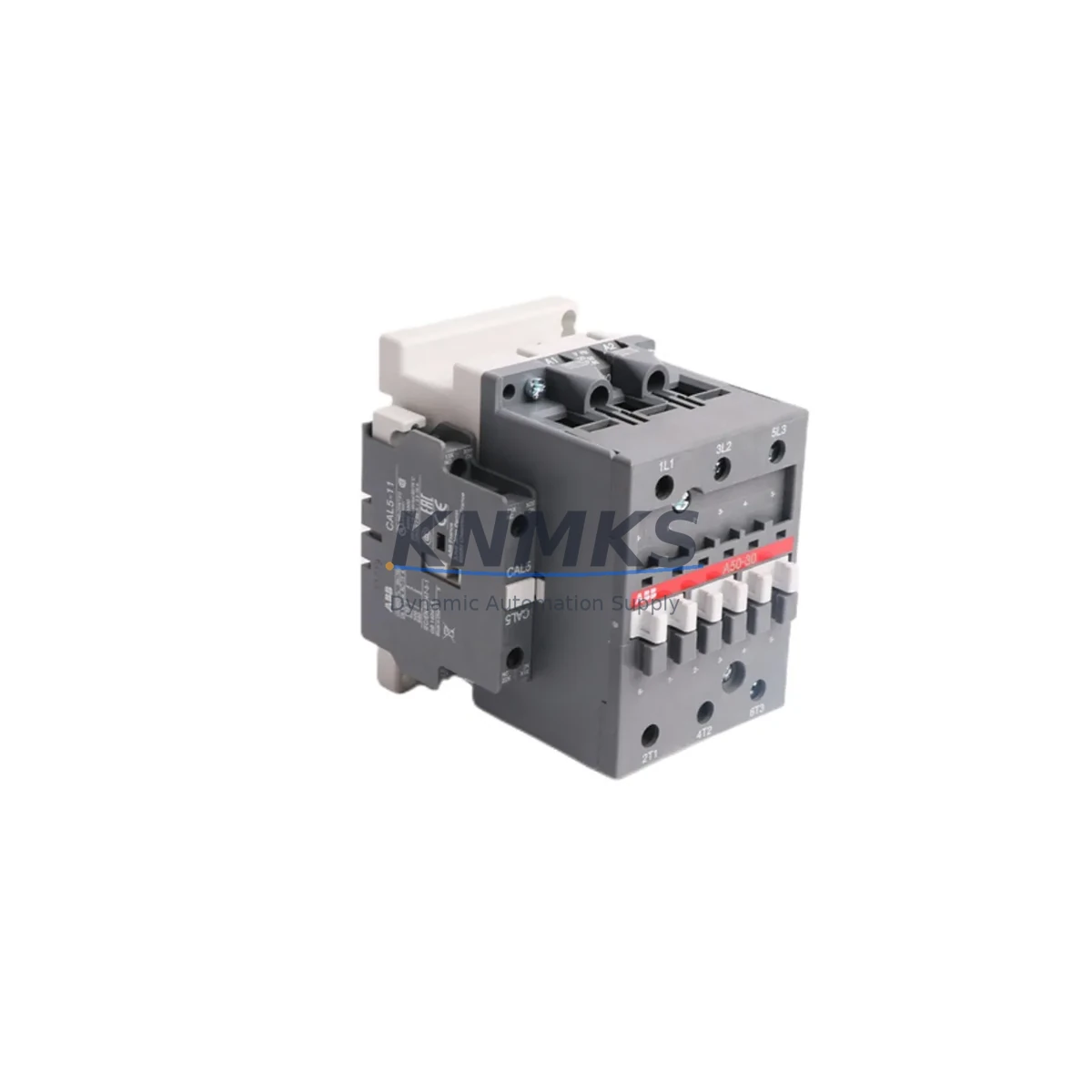
ABB A50-30-11 1SBL351001R8011 Migration-Ready DC Contactor for Legacy Control Systems
The ABB A50-30-11 (Part No. 1SBL351001R8011) is a heavy-duty DC contactor from ABB’s A-Line series, engineered for demanding industrial switching applications in legacy and modernized control environments. With a rated operational current of 50 A and a three-pole main contact configuration (3NO + 1NO + 1NC auxiliary), this contactor is a proven workhorse in motor control centers, drive panels, battery-backed DC bus systems, and retrofit control cabinets across manufacturing, energy, and process industries.
As legacy automation platforms age and OEM support windows close, procurement and maintenance teams face increasing pressure to source verified drop-in replacements that preserve existing wiring layouts, DIN rail footprints, and coil voltage specifications. The A50-30-11 addresses this directly: its terminal pitch, mounting dimensions, and coil interface are fully consistent with earlier A-Line contactor generations, making it a reliable migration component when upgrading or restoring aging control panels without full redesign.
Before installation in a retrofit scenario, engineers should confirm the coil supply voltage against the existing control circuit — the A50-30-11 is available in multiple coil voltage variants, and selecting the correct suffix is critical to avoid coil burnout or failure to pick up. Terminal torque specifications must be respected during rewiring; over-torquing on legacy copper lugs can cause terminal cracking, while under-torquing leads to resistive heating at load contacts. If the original panel used an ABB A40 or A45 contactor in the same slot, verify that the auxiliary contact block arrangement matches, as auxiliary block compatibility affects PLC input card wiring and interlock logic without requiring program changes.
In systems where the A50-30-11 is used alongside an ABB PSR or PSE soft starter, confirm that the bypass contactor timing relay settings are preserved during replacement. Soft starter bypass applications require the contactor to close within a defined window after motor run-up; any deviation caused by a coil voltage mismatch or auxiliary contact delay can trigger a fault on the soft starter’s output relay, causing nuisance trips. Similarly, if the contactor is part of a reversing starter circuit using two interlocked A50-30-11 units, the mechanical interlock bridge (if originally fitted) must be reinstalled on the replacement unit — electrical interlock alone through the PLC I/O is insufficient for safety-rated reversing applications.
For panels incorporating an ABB S-series MCCB or MS-series motor protection relay upstream of the contactor, verify that the short-circuit coordination class (Type 1 or Type 2) is maintained after replacement. Type 2 coordination requires that neither the contactor nor the overload relay sustains damage under short-circuit conditions — a requirement that must be re-validated if the upstream protective device rating has changed since the original panel was commissioned. Coordination tables in the ABB Low Voltage Products catalog provide the verified combinations.
When the A50-30-11 is installed in a DC bus switching application — common in battery storage systems, UPS bypass panels, and traction control cabinets — pay close attention to the DC breaking capacity rating. DC arc extinction is significantly more demanding than AC, and the contactor’s rated DC breaking capacity must exceed the prospective fault current at the point of installation. If the original system used an AC-rated contactor in a DC application (a common legacy error), the A50-30-11 provides a correctly rated replacement that eliminates the arc flash risk associated with undersized DC switching devices.
Panels that include an ABB CP-series 24 VDC power supply module feeding the control circuit should have their output current capacity verified before adding the A50-30-11’s coil inrush to the load. Contactor coil inrush current at pickup can be 6–10× the sealed current; if multiple contactors are energized simultaneously during a system restart sequence, the 24 V rail may sag below the minimum hold-in voltage, causing contactors to drop out immediately after pickup. Staggering the energization sequence in the PLC program or adding a dedicated coil supply rail resolves this without hardware changes.
For systems using PROFIBUS DP or PROFINET I/O modules to monitor contactor auxiliary contacts, confirm that the I/O module’s input filter time is set appropriately for the contactor’s bounce characteristics. Auxiliary contact bounce on pickup and dropout can generate false edge transitions on fast digital input modules, causing spurious fault logs or interlock state errors in the SCADA system. A filter time of 3–5 ms is typically sufficient to suppress bounce without masking legitimate state changes.
All units supplied by KNMKS are sourced from authorized distribution channels, individually inspected prior to dispatch, and covered by a support terms confirmed by quotation against manufacturing defects. Stock is maintained for immediate shipment, supporting both planned retrofit schedules and emergency breakdown replacements where minimizing control system downtime is the primary constraint.
Migration Compatibility Table
| Parameter | Detail |
|---|---|
| SKU / Part Number | A50-30-11 / 1SBL351001R8011 |
| Brand / Series | ABB / A-Line |
| Main Contacts | 3NO (50 A rated operational current) |
| Auxiliary Contacts | 1NO + 1NC (integrated) |
| Mounting | DIN rail or screw mounting; compatible with A-Line mounting accessories |
| Mechanical Interlock | Compatible with ABB mechanical interlock bridge for reversing applications |
| Auxiliary Block Compatibility | Compatible with ABB CA5 / CAL5 auxiliary contact blocks |
| Upstream Coordination | Verified with ABB S-series MCCB and MS-series motor protection relays (Type 1 & Type 2) |
| DC Switching | Rated DC breaking capacity; suitable for battery, UPS, and traction DC bus applications |
| Communication Monitoring | Auxiliary contacts compatible with PROFIBUS DP / PROFINET digital input modules |
| Retrofit Drop-In | Direct replacement for A40 / A45 / A50 legacy units (verify coil voltage suffix) |
| Country of Origin | Germany |
| Support terms | 12 months from date of shipment |
| Availability | availability confirmed by RFQ — ready for immediate dispatch |
Retrofit Planning for Existing Automation Systems
A successful retrofit begins with a complete audit of the existing control cabinet before any components are removed. Document the existing terminal wiring using the original panel drawings or, where drawings are unavailable, photograph each terminal block row before disconnection. For panels using ABB SNK or UK-series terminal blocks, note the wire ferrule sizes and terminal positions — the A50-30-11’s main terminal accepts conductors up to 35 mm², but legacy panels wired with older insulation types may require ferrule replacement to meet current installation standards.
If the panel includes an ABB UMC100 or UMC22-FBP motor management relay monitoring the contactor’s auxiliary contacts for run feedback, verify that the replacement contactor’s auxiliary contact response time falls within the UMC’s configurable feedback timeout window. Exceeding this window causes the UMC to log a wiring fault and inhibit further start commands until the fault is acknowledged — a situation that can be misdiagnosed as a PLC program error during commissioning.
For cabinets where an ABB ACH580 or ACS880 variable frequency drive controls the motor and the A50-30-11 serves as the input isolation or bypass contactor, confirm that the drive’s input filter capacitors are fully discharged before the contactor is closed onto a de-energized bus. Closing a contactor onto a charged capacitor bank without a pre-charge resistor can generate an inrush current spike that welds the contactor’s main contacts on the first operation — a failure mode that is not covered under support terms and requires complete contactor replacement.
Where the retrofit involves replacing multiple contactors across a multi-tier motor control center (MCC), plan the replacement sequence to maintain partial system availability. Replace contactors in non-critical circuits first, validate operation under load, then proceed to critical circuits during a scheduled maintenance window. This staged approach limits exposure and allows the maintenance team to identify any wiring discrepancies before the full system is returned to service.
Downtime Control During System Migration
Minimizing control system downtime during a contactor replacement requires preparation that begins before the maintenance window opens. The replacement A50-30-11 should be bench-tested for coil pickup and dropout voltage, auxiliary contact continuity, and main contact resistance before it enters the panel. A simple 24 VDC bench test using a current-limited power supply confirms coil function; main contact resistance should be below 100 µΩ when measured with a micro-ohmmeter under light contact pressure.
Before disconnecting the original contactor, photograph or sketch the auxiliary contact wiring, noting which terminals connect to PLC input cards, interlock circuits, and indicator lamp circuits. Auxiliary contact wiring errors are the most common cause of extended commissioning time after a contactor replacement — a single transposed wire can invert a run-feedback signal, causing the PLC to command a second start attempt immediately after the first, resulting in a motor protection trip.
Where the system uses a PROFINET or EtherNet/IP network for I/O communication, place the affected I/O module in forced-output mode (if the PLC platform supports it) before disconnecting the contactor. This prevents the PLC from reacting to the loss of auxiliary contact feedback during the physical replacement and avoids triggering downstream interlocks or safety functions that could extend the outage beyond the planned window.
After installation, perform a no-load test before reconnecting the motor load: energize the coil, verify auxiliary contact state changes at the PLC I/O display, and confirm that the mechanical interlock (if fitted) prevents simultaneous closure of both contactors in a reversing pair. Only after no-load validation is confirmed should the main circuit be re-energized and the motor started under load. This sequence protects both the replacement contactor and the connected equipment from damage caused by wiring errors that were not caught during the physical installation.
Retrofit Support FAQ
Q1: Is the ABB A50-30-11 (1SBL351001R8011) a direct replacement for the A50-30-10 or A50-30-01?
The A50-30-11 carries one NO and one NC auxiliary contact integrated into the body. The A50-30-10 has one NO only, and the A50-30-01 has one NC only. If your existing panel wiring uses only one auxiliary contact polarity, the A50-30-11 is electrically compatible — the unused auxiliary terminal can be left unwired. Confirm that the additional auxiliary terminal does not create a short-circuit path against adjacent wiring before closing the panel.
Q2: What pre-shipment testing is performed on each unit?
Each A50-30-11 supplied by KNMKS is inspected for physical integrity, coil resistance within manufacturer tolerance, and auxiliary contact continuity prior to dispatch. Units are packaged in anti-static, impact-resistant packaging suitable for international freight. A support terms confirmed by quotation cover manufacturing defects from the date of shipment.
Q3: Can the A50-30-11 be used in a DC coil application if the panel operates on a 24 VDC control rail?
Yes, provided the correct coil voltage variant is selected. The A-Line series is available with AC and DC coil options across multiple voltage ratings. Confirm the coil voltage suffix in the full part number before ordering. Operating an AC-rated coil on a DC supply (or vice versa) will result in coil failure and is not covered under support terms.
Q4: What is the typical lead time, and is stock available for emergency breakdown orders?
KNMKS maintains inventory of the A50-30-11 for immediate dispatch. Standard orders ship within 1–2 business days. For emergency breakdown requirements, contact the sales team directly to confirm real-time stock availability and expedited shipping options.
© 2026 KNMKS. All rights reserved.
Original Source: https://knmks.com
Contact: admin@knmks.com | +86 18359268345
Product Identification
- Brand / Ecosystem
-
ABB
ABB - Model / Series
- A50-30-11 1SBL351001R8011
- Product Family
- Relays & Interface
- Availability Status
- Available on request after model and quantity confirmation
- Inquiry Type
- B2B RFQ, replacement inquiry and project spare-part request
- Pre-Quote Check
- Exact SKU, brand, series, quantity, nameplate photos and destination country are checked before quotation
System Path
Where this product fits in the KNMKS automation structure.
Specification & Inquiry Focus
- Interface range
- Relays, isolation and signal modules
- Common needs
- Coil voltage and contact rating
- Project support
- Panel wiring and signal protection
Buyer Confirmation
Information KNMKS checks before replying.
- Exact model
- A50-30-11 1SBL351001R8011
- Brand / ecosystem
- ABB
- Product family
- Relays & Interface
- Application note
- Replacement, maintenance, project build or spare-part list
- Useful photos
- Nameplate, installed unit, cabinet layout or connector side
- Delivery details
- Quantity, destination country and target schedule
Document Support
Files and notes can be confirmed during quotation.
- Product photos or nameplate confirmation when available
- Packing and delivery notes before quotation confirmation
- Support scope and delivery terms confirmed per inquiry
- Export document coordination for qualified B2B requests
Inquiry Support
- Relay base and module matching
- Signal isolation and protection options
- Panel accessory inquiry support
What to Send Us
- Brand and exact model number: ABB A50-30-11 1SBL351001R8011
- Quantity and required delivery time
- Application, replacement requirement or nameplate photo
- Destination country and shipping preference
RFQ Preparation
This is a product inquiry page built for RFQ communication.
Fast Model Check
Send this model to KNMKS for confirmation.
Include quantity, destination country and photos if this is a maintenance replacement. The inquiry will be saved with a reference number after submission.
Brand & Compatibility Note
KNMKS displays automation product information for well-known industrial brand ecosystems and compatible replacement references. Brand names are used for product identification and compatibility reference only; final availability and commercial terms are confirmed per quotation.
 Manufacturing
 Machine Tools
 Packaging
 Energy & Power
 PLCs & Controllers
 HMI & Displays
 Servo Systems
 Variable Frequency Drives